• The move to the new server is done. There are some software and database maintenance updates in process. This has us passing the hat around to help out. We appreciate any donations. Seriously, even a dollar helps. The payment page may be found here - https://www.audiokarma.org/support.html

Heathkit AR-1500 with Thermal Runaway

JD Harvey

Galvanized Ear
Main issue... thermal runaway on TO-3 Q706 with a bias of 79mv across emitter resistors.

My neighbor asked me if I'd replace the electrolytics in his Heathkit AR-1500. He stated the left channel had suddenly stopped playing music and it's time for a refresh. He's the kit builder and owner since 1971/1972.

I replaced all of the electrolytes and the left channel came back to life, but with thermal runaway on T-O3 Q706.

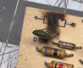
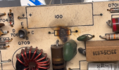
**IMPORTANT** The board has signs of burning/extreme heat on C721,R733, Q709, so the thermal runaway had been an unknown issue for quite some time. Probably years.

Without knowing what's causing the thermal runaway, I decided to continue the refresh replacing the following parts and see what happens.

All Electrolytics
All diodes replaced with type 1N4148 including three 1N4148 in series to replace D703
Resistors R721, R705, R733, R723, R735, R749, R751, R745, R743
All film caps C721, C729, C725, C723, C727
Drivers Q704, Q705 with MJE243G / MJE253G
T-O3 Outputs Q706, Q707 with MJ21194G

After replacing these parts the issue remains unchanged.

After reading threads on AK I decided to experiment with values on
(R721) 22ohms... I tried the following 10ohm, 1ohm, 68ohm & 47ohm. No luck.
(R719) 3.3k.... I tried 4.7k... No luck.
(R705) 10k.... I tried 4.7k and 22k with no luck.
--------------------------------------------------------------------------------------------------------------------------------------

Voltages on a 113w dim bulb
I can take it off the bulb and get voltages if it would help, just trying to be safe.

C721 0.756v

R721 1.93v
R727 0.55v
R733 0.730v
R719 21.19v
R711 21.17v
R731 0.782v
R709 37.7v
R705 36.4v

D703 1.8v 0.14v
D701 37.77v 36.01v
D702 1.57v 1.95

Q701 E0.651v C36v B0.76v
Q702 E0.68v B0.09v C37.53v
Q703 E37.42v B36.08v C2.9v
Q707 B0.769v E0.723v C1.61v
Q708 B0.769v E0.730v C1.59v
Q709 B0.731v E0.730v C0.102v
Q706 T-O3 B1.952v C37.29v E1.34v

Other information. I have the manual.

Any help would be greatly appreciated.

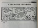
IMG_3533.jpeg

IMG_3256.jpeg

IMG_3607.jpeg
 
Last edited:
Register to hide this ad
I suggest that you look at the installed components and compare against the schematic or build document if you have it. While it was a kit built in 73, it was a kit, and makes sense to verify that all was done properly (transistor pinouts, diode polarity, resistor valuse etc.
I also think your readings are off
Q701 E0.651v C36v B0.76v
Q702 E36.6v B0.065v C37.53v
It almost seems as if Q701 E and Q702E are not connected as they should be according to the schematic. Maybe there is a bad connection (maybe a jumper wire missing). Recheck the voltages and then use an ohm meter (with power off) to check E of q701 to E of Q702 to verify they are connected
 
Last edited:
Hey Tom. I had the voltages for B & E swapped on Q702. Oops.. ;) Good observation. Thanks.
Corrected in the original post. Q702 E0.68v B0.09v C37.53v
Checked Q701 E to Q702 E and they are connected.

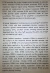
I found this information in the service manual. Great find!

IMG_3609.jpeg

IMG_3610.jpeg
 
Without knowing what's causing the thermal runaway
I'd find the cause for that first. Usually high quiescent current through the output transistors is caused by bias voltage being too high. And this is then caused by the thermal diode D703 being bad/open. Keep it on DBT for now and measure the voltage between the bases of Q704 and -5. It is likely higher than 2.4 V.
 

Attachments

Hey PE9ZZ.
D703 tested out of circuit fine. I decided to put three 1N4148 in series. This had little to no effect.
I decided to replace all of the diodes with 1N14148. No change.

On 113w DBT
Q704 Base is 0.621v
Q705 Base is 0.728v

Thanks
 
On 113w DBT
Q704 Base is 0.621v
Q705 Base is 0.728v
Huh?!?!? Q705 base is higher than Q704's?!?!? That doesn't make any sense. Could be Q705 is shorted. Is DBT glowing? What is the voltage across R744? And R746?
 
measure the voltage between the bases of Q704 and -5. It is likely higher than 2.4 V.
Between the bases - that's from the base of Q704 to the base of Q705.
Q704 Base is 0.621v
Q705 Base is 0.728v
This looks like a measurement from B to E for those two transistors.

The voltage reading requested is very important, it is the single voltage measurement that can explain the high bias current. The lower this voltage is the lower the bias current flowing in the driver transistors and the output transistors.
 
What is the voltage across R744? And R746?
That should be R743 and -5 because the fault is in the left channel. The voltage was reported above as 79 mV (emitter resistors) which is almost a quarter of an amp which must certainly make the bulb glow. But not really bright. Anyway, the figures are not reliable enough to make a proper assessment of the issue at hand here. The diode D703 seems to have no thermal coupling with the output transistors which also makes thermal instability likely. The reported burnt components make no sense as these are at different locations in the schematic.

But let's start with the voltage between the bases of Q704 and -5. This is what determines the quiescent current through the output transistors.
 
Huh?!?!? Q705 base is higher than Q704's?!?!? That doesn't make any sense. Could be Q705 is shorted. Is DBT glowing? What is the voltage across R744? And R746?
That should be R743 and -5 because the fault is in the left channel. The voltage was reported above as 79 mV (emitter resistors) which is almost a quarter of an amp which must certainly make the bulb glow. But not really bright. Anyway, the figures are not reliable enough to make a proper assessment of the issue at hand here. The diode D703 seems to have no thermal coupling with the output transistors which also makes thermal instability likely. The reported burnt components make no sense as these are at different locations in the schematic.

But let's start with the voltage between the bases of Q704 and -5. This is what determines the quiescent current through the output transistors.
I was measuring to ground. I misunderstood. It's -2.152 between the bases of Q704 & Q705

The 79mv is off the DBT. On the DBT with 113w bulb, it's settling at 60.4mv. This is measuring across R743 & R745

The burning was on R721 & R733. It appeared to be C721 but R721 makes more sense after closer inspection. A new R721 (22Ω) and R733 (68Ω) has been replaced. The old resistors tested close to accurate, even after the heat.

D703 tested good, but I decided to replace it with three 1N4148 in series. I can reinstall the original D703 at your discretion.

Bulb is out

***Note** The thermal runaway was present before anything was done, so the new parts didn't create a new issue. The owner/builder said music on the left channel suddenly stopped a few weeks ago. I replaced all electrolytics, music returned and sounded fine. I replaced R721 & R733 because of the heat they endured. Then noticed Q706 getting blistering hot. I thought maybe the carbon resistors drifted out, so I replaced them, along with a few other parts for good measure. Problem has persisted. :dunno:

Thanks for your patience as I learn.

Screenshot 2026-11 at 11.46.31 AM.png

IMG_3636.jpeg


Screenshot 2026-06-11 at 10.33.50 AM.png


Screenshot 2026-06-11 at 10.32.52 AM.png


IMG_3627.jpeg
 
Last edited:
Is D703 attached to the heat sink? It won't track properly without good thermal coupling. The closer to the output transistors the better, generally speaking.
 
Is D703 attached to the heat sink? It won't track properly without good thermal coupling. The closer to the output transistors the better, generally speaking.
It isn't. This is a design flaw. Note there is no bias adjustment so the large quiescent current of 79/0.33=0.24 A could be intentional. Some Philips amps also have an almost class A bias.
It's -2.152 between the bases of Q704 & Q705
2.2 V Is not excessive. Leave the diodes in.

If Q706 gets really hot the same must be true for Q707. If not the thermal compound could be dried out.

If you want to reduce bias current just steal current away from D703 by shunting it with a 1k trimmer potmeter. This will lower the bias voltage and thus the current through Q706/7. Quiescent current will still runaway but not as much.
 
The right channel bias is 14mv. Also both output TO-3 are 88 degrees under light load on the right channel..

Left channel... Q707 isn't hot at all. About 89 degrees, while Q706 is 140 ish, but thats on DBT. Off it, Q706 gets even hotter! They both have excellent thermal contact so does Q704 & Q705. The heatsink around Q706 gets nice and toasty.

This has been the craziest issue. I hate to hand it back to my neighbor saying that's just the way it is. I may replace all of the resistors and cross my fingers.

Do you think changing R737 (100Ω) to 150Ω or 220Ω would help?

Thanks for your help.
 
Last edited:
I would lower it, not make it larger. Only it won't help because this resistor only serves to discharge the base capacitance of Q706L.

But first figure out why Q706L gets so hot. Is the output voltage zero? Power rails OK? What are the voltages across R743 and -5? The values in the schematic are inconsistent. Emitter of Q706L +0.1 V and Q707L -0.6 V? That doesn't make any sense. Does the manual say anything about emitter current of these transistors? (I am lazy)
 
It isn't. This is a design flaw. Note there is no bias adjustment so the large quiescent current of 79/0.33=0.24 A could be intentional. Some Philips amps also have an almost class A bias.
yeah I saw the fixed resistor in series with it on the schematic. I might consider changing both of those things, and maybe looking at the AR1500A to see what differences / improvements may exist that might be applicable here. I know nothing about either unit so this is pure speculation. For all I know the circuits are completely different.
 
Power rails are good. It's 100% in the Left amplifier board. The voltages are indeed crazy.

Left Channel:
Across R743 & R745 emitters its 60mv on 113w DBT.
Without DBT, 79mv

Right Channel:
Across R744 & R746 emitters, 14mv

As for schematic voltages on Emitters Q706L +0.1 V and Q707L -0.6 V. I think that's right, because this is a quasi complementary design. All outputs are NPN TO-3. Also that's measuring to ground.
 
Last edited:
As for schematic voltages on Emitters Q706L +0.1 V and Q707L -0.6 V. I think that's right, because this is a quasi complementary design.
It isn't. Even a quasi complimentary design has the same currents through the emitter resistors. Or in this case emitter/collector resistors, R743/-5. Unless the output voltage is not zero but in any case it should be close to zero. I have seen many errors in schematics and this must be one of them.

The only thing that could cause such a big difference in bias current is base-emitter voltages that are different between the two channels. Being Q704, -5 and -6. The Sziklai pair Q705/-7 only has the first base-emitter junction to be relevant. If there are different types of transistors used that could be the cause. Again, the original design does not have a bias current adjustment and you could use my suggestion above to reduce it.
 
Ok. Got ya. I've had a difficult time finding knowledge and good documentation on the AR1500. The manual is useful, but has wacky diagnosing techniques using the onboard tester. They assume the builder or technician doesn't own a multimeter.

Never invested so much time chasing a problem without a solution. I may try adding a 1k pot at D703. This thing went from a simple recap to endless nightmare POS. Heathkit has left a bad taste in my mouth.

Thank you for your time and patience. :thumbsup:
 
I might consider changing both of those things, and maybe looking at the AR1500A to see what differences / improvements may exist that might be applicable here. I know nothing about either unit so this is pure speculation. For all I know the circuits are completely different.
I'm not skilled enough to turn a lemon into lemonade. Haha! ;)
 
mounting the diodes to the heat sink wouldn't be real difficult, just need to tap a hole if the isn't one and work out some sort of clamping arrangement. The idea is to have the diodes at a similar temperature to the transistors so the voltage drop across the diodes changes with the output transistors and keeps it overall more stable. Otherwise as the transistors get hotter, they will tend to conduct more current as the voltage drop across the junctions gets lower.

To make it adjustable maybe sub that 22 ohm for a 15 ohm plus a 25-50 ohm pot in series. That would give you a bias adjustment instead of just whatever it is.
 
this may also be of some use, post 12 has the differences called out.


I'm not smart enough to be able to explain what those changes will do for it though so not a clue if maybe they will make this less inclined to toast itself. A couple of those parts look like they may be for high frequency stability though. If this is oscillating it will certainly make a ton of heat.
 
Back
Top Bottom