• The move to the new server is done. There are some software and database maintenance updates in process. This has us passing the hat around to help out. We appreciate any donations. Seriously, even a dollar helps. The payment page may be found here - https://www.audiokarma.org/support.html

Heathkit W-5M Rebuilds

Defeño

Active Member
It's amplifier day here in Boston. What that means I that I just took delivery of a pair of Heathkit W-5Ms that I ordered off of eBay about a week ago. I had been mulling the purchase of such an amplifier for a while now. Initially I was attracted by the tube cage design (I know, random, huh?) but then the more I read the more I heard that this is a very nice amp.

So I bid on a pair on eBay. Here's the original listing:
They both appeared to be in pretty nice, mostly original condition. Yeah, someone had changed the input jack to a 1/4" TRS connector, and also made the output the same. But otherwise the units look very clean. They have the Peerless 16458 output transformers. The rectifier tubes are a pair of old RCA tubes, though the tube number has worn off. The input tubes are a pair of Mullard 12AU7s, while the output tubes are a pair of Tung Sol 5881s. I'm wondering if I'd be better off with KT66s which are the original spec.

So what I'm hoping to do with this thread is a few things. First, I'll share my journey with these babies and provide some "tube porn," for those of us who enjoy rebuilds of cranky old equipment. Second, I'm hoping to solicit some advice from the electrical engineers and other knowledgeable folks here about things like replacement capacitors, tubes, solid state rectification, thermistors, etc.

I've got a mostly-completed shopping cart at Digikey, but still need to add power supply capacitors. So capacitor questions will be some of my first.

Thanks for reading along,

Kim G
Boston, MA
Where I'm currently listening to a 1968 Dynaco ST-70 with the VTA/Tubes4HiFi input board.

Initial Unboxing
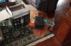
_MG_4491.JPG

Twins Separated at Birth
_MG_4498.JPG


My Transformers are Better than Dreamworks'
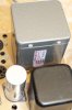
_MG_4496.JPG


Input/Output Weirdness. This is on the list to fix
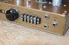
_MG_4499.JPG
The preamp plug has been changed to a switch which connects the selected impedance to the two TRS jacks to the left of the input. Based on visual inspection, I can already tell that this switch is noisy as it has a loose center connection. Question: WTF was the guy who did this thinking???

Otherwise the Back Panel Looks Pretty Good
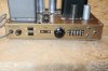
_MG_4500.JPG

Innards have been somewhat modified, but no thoroughgoing recap/ re-resistoring has been done
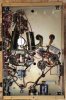
_MG_4503.JPG
Mismatched capacitors at lower left are sure sign of quality!


Second amp has more original-looking capacitors, and one obviously newer one
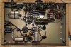
_MG_4506.JPG

First order of business: Flatten one lower cover
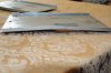
_MG_4507.JPG

Flattened in No Time Flat. It's nice to have a rubber hammer and a steel plate. Wish the rest were so easy!
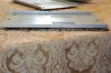
_MG_4508.JPG

Output Tubes, Tung Sol 5881. Are these good? (Assuming they work)
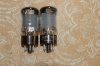
_MG_4511.JPG

A couple more pictures to follow, but I've reached my limit with this post.
 
Last edited:
Register to hide this ad
It's amplifier day here in Boston. What that means I that I just took delivery of a pair of Heathkit W-5Ms that I ordered off of eBay about a week ago. I had been mulling the purchase of such an amplifier for a while now. Initially I was attracted by the tube cage design (I know, random, huh?) but then the more I read the more I heard that this is a very nice amp.

So I bid on a pair on eBay. Here's the original listing:
They both appeared to be in pretty nice, mostly original condition. Yeah, someone had changed the input jack to a 1/4" TRS connector, and also made the output the same. But otherwise the units look very clean. They have the Peerless 16458 output transformers. The rectifier tubes are a pair of old RCA tubes, though the tube number has worn off. The input tubes are a pair of Mullard 12AU7s, while the output tubes are a pair of Tung Sol 5881s. I'm wondering if I'd be better off with KT66s which are the original spec.

So what I'm hoping to do with this thread is a few things. First, I'll share my journey with these babies and provide some "tube porn," for those of us who enjoy rebuilds of cranky old equipment. Second, I'm hoping to solicit some advice from the electrical engineers and other knowledgeable folks here about things like replacement capacitors, tubes, solid state rectification, thermistors, etc.

I've got a mostly-completed shopping cart at Digikey, but still need to add power supply capacitors. So capacitor questions will be some of my first.

Thanks for reading along,

Kim G
Boston, MA
Where I'm currently listening to a 1968 Dynaco ST-70 with the VTA/Tubes4HiFi input board.

Initial Unboxing
View attachment 1816653

Twins Separated at Birth
View attachment 1816654


My Transformers are Better than Dreamworks'
View attachment 1816657


Input/Output Weirdness. This is on the list to fix
View attachment 1816659
The preamp plug has been changed to a switch which connects the selected impedance to the two TRS jacks to the left of the input. Based on visual inspection, I can already tell that this switch is noisy as it has a loose center connection. Question: WTF was the guy who did this thinking???

Otherwise the Back Panel Looks Pretty Good
View attachment 1816662

Innards have been somewhat modified, but no thoroughgoing recap/ re-resistoring has been done
View attachment 1816663
Mismatched capacitors at lower left are sure sign of quality!


Second amp has more original-looking capacitors, and one obviously newer one
View attachment 1816666

First order of business: Flatten one lower cover
View attachment 1816673

Flattened in No Time Flat. It's nice to have a rubber hammer and a steel plate. Wish the rest were so easy!
View attachment 1816674

Output Tubes, Tung Sol 4881. Are these good? (Assuming they work)
View attachment 1816677

A couple more pictures to follow, but I've reached my limit with this post.
Tung Sol 5881, Superb if good.
 
So my first order of business is the following:

Install a thermistor to reduce inrush current and help to protect the possibly finicky power transformer. These have a reputation for dying, and I was a little dismayed to see that no one has ever installed either a surgistor or a thermistor. So despite the seller saying the units were looked over by a tech and pronounced in working order. I have yet to plug them in. I did go through one of them with an ohm meter measuring capacitors. Most read >200K Ω resistance. This strikes me as a little low, e.g., a bit leaky, but not a disaster in the short term.

Question: What value of thermistor should I choose? I'm thinking something along the lines of 50 Ω @ 3A.

Replace all of the power supply capacitors. Sheldon Stokes of QuadESL.com has designed a board which replaces all of the power supply capacitors. But this board is not in production and getting a pair made (board only) would cost me $120, so I'm toying with the idea of simply recreating the capacitor set on a perf board. I can get 2 of those for about $10 on Amazon, and the additional work of doing the wiring strikes me as pretty minor.

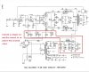
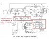
I'm hoping to replace the circled caps with a capacitor board, of course keeping the existing choke.
Heathkit W-5M Schematic Caps Circled.jpg
Question: Should I put some kind of low value (like 0.1 mfd) bypass cap in series with the caps feeding the input stage?

I'm also wondering about dropping a solid state bridge rectifier onto my cap board and doing away with the rectifier tube. Aside from questions of voltage drop, is there anything else I'd need to worry about if I wanted to do this?
 
First, those are in very, very nice condition. I would definitely go with the Stokes PS design, or basically a bank of stacked electrolytics for several reasons, one being that you want a lot of headroom in the PS caps, at least 600VDC, though a thermistor will help. It will also sound better than can caps. I just added capacitor banks to a pair of Heathkit W4's I've been working on, along with updated coupling caps and resistors, and they went from "okay" to really stunning--I'm shocked at how good they sound.

Also replace the coupling caps with 630VDC ones. I don't know if Dave Gillespie would agree, but reversing the order of the coupling caps, 1uF first then .1 second, is a trick he uses in his other Heathkit mods to improve low-frequency stability. Not sure if it's "blessed" for these, perhaps he can advise.

I would NOT use SS rectifiers. Apart from altering the sound, you're inviting a host of other issues, IMO. The 5R4 is a beautiful rectifier, leave them in place.

Other than that, check the resistor values, and if they're within 10% I would leave them rather than trying to hack up the amp right away. Down the road you can spruce them up with tight-tolerance metals films or whatever.
 
Last edited:
@battradio had a recommendation for derating the PS voltage with a choke input mod to destress the trannys. I think it involved using a 600 Volt film cap only before the choke from the rectifier.
 
Hey @zackthedog,

Thanks for the suggestions. A couple of months ago I installed a cap board in my ST-70, and despite the fact that the can cap was new-ish (maybe a year old), the cap board notably improved the sound. I don't know enough about engineering to know if this is true, but I think modern, separate electrolytics are faster than the old can caps. Which is to say that I believe they charge and discharge faster, which if true, would explain how they can clean up the sound.

As for the resistors, I have a cart full of metal film, high-precision resistors at Digikey. Yes, it'll be a pain in the ass to replace them, but I've got to imagine that fresh, high precision resistors will clean up the sound a lot. These amps need to sound materially better than my ST-70 to have made this worthwhile.

As for the output tubes, thanks. I got a PM from someone basically saying the same. Putting in the OEM recommended tube was my inclination all along; looks like folks agree with this.

As for the condition, yes they are in very nice condition. The only notable exception is the holes drilled for those TRS jacks for the speakers. Hopefully I can find some kind of button to fill their place. I just removed two, and it looks bad. Maybe I put them back. Although the innards are somewhat in the way.

Thanks and have a great day!

Kim
 
Sheldon Stokes has a nice cap board design.
https://www.quadesl.com/refurbishment/refurb_heathW5M.html

Nice project. Have fun with it. I'm envious already.
John
Hi John,

Thanks. Yes he has a nice cap board, though it is essentially what I've outlined in red above. He doesn't have any in stock, though he put the design up on www.oshpark.com, which will make me 3 of them for $120. Given that I can get double-sided, plated through-hole perf board for about $8 for each 4"x6" size I'll need, I'm tempted to go that route. Electronically it'll be the same, though it won't look quite so nice. But how often do you look inside your amp? Hopefully it's seldom.

Cheers,

Kim
 
Hey @zackthedog,

Thanks for the suggestions. A couple of months ago I installed a cap board in my ST-70, and despite the fact that the can cap was new-ish (maybe a year old), the cap board notably improved the sound. I don't know enough about engineering to know if this is true, but I think modern, separate electrolytics are faster than the old can caps. Which is to say that I believe they charge and discharge faster, which if true, would explain how they can clean up the sound.

As for the resistors, I have a cart full of metal film, high-precision resistors at Digikey. Yes, it'll be a pain in the ass to replace them, but I've got to imagine that fresh, high precision resistors will clean up the sound a lot. These amps need to sound materially better than my ST-70 to have made this worthwhile.

As for the output tubes, thanks. I got a PM from someone basically saying the same. Putting in the OEM recommended tube was my inclination all along; looks like folks agree with this.

As for the condition, yes they are in very nice condition. The only notable exception is the holes drilled for those TRS jacks for the speakers. Hopefully I can find some kind of button to fill their place. I just removed two, and it looks bad. Maybe I put them back. Although the innards are somewhat in the way.

Thanks and have a great day!

Kim

Heavy-duty binding posts will fit in those holes perfectly, that's what I did with my W4s. Like these:

https://www.amazon.com/Viborg-Bindi...s=Copper+binding+posts&qid=1585957603&sr=8-14
 
...and those are interesting caps on the pre-amp sockets. By any chance do they act as an on-off switch?
 
...and those are interesting caps on the pre-amp sockets. By any chance do they act as an on-off switch?
The preamp sockets have been converted to a rotary switch which you can use to set the output impedance. This is connected to two TRS jacks for the speakers. I'm wondering if maybe these amps were used somewhere that they were selling loudspeakers. Otherwise why would you need a quick-connect for the speakers? On the other hand, who would be demonstrating speakers with a 25 watt amplifier? Mysteries abound.
 
Heavy-duty binding posts will fit in those holes perfectly, that's what I did with my W4s. Like these:

https://www.amazon.com/Viborg-Bindi...s=Copper+binding+posts&qid=1585957603&sr=8-14

That's quite a good idea. Even though I'm a fan of terminal strips, the binding posts would fit those holes and would be an appropriate look for the back of an amplifier. Thanks!

Edit: the holes measure 11 mm, while the binding posts are 8mm. Still, maybe some kind of grommet would fill the gap. I'll look into this.
 
That's quite a good idea. Even though I'm a fan of terminal strips, the binding posts would fit those holes and would be an appropriate look for the back of an amplifier. Thanks!

Edit: the holes measure 11 mm, while the binding posts are 8mm. Still, maybe some kind of grommet would fill the gap. I'll look into this.

The binding posts come with spacer/insulators that fit those holes very nicely, just a little wiggle room.
 
Hey all!

I was really hoping to get some suggestions about increasing capacitance on my power supply. I'm going to replace the "can" and other electrolytics with modern, axial-lead electrolytics built on perf board. I'd like to take the opportunity to increase the capacitance, but have a couple questions:

1) Is it worth the risk to increase the capacitance on the circled areas on the schematic?
2) How much can I up the capacitance without unduly straining the power transformer on startup?
3) Can you suggest any resources I could read to learn how to make a proper calculation?

Any other helpful tips on this part of the amp would be much appreciated!

Thanks,

Kim G
Boston, MA
Boston, MAHeathkit W-5M Schematic Caps Circled.jpg
 
Imho, increasing the 20uF caps for PI and driver stages, or the common cap that is separated by the 100 ohm dropper, are not a concern.

Increasing the input stage supply cap may be a concern as it may have been designed to tailor the low frequency response for stability. That concern would be diminished if you added a low frequency shelf network for improved stability.

Increasing the CLC filter caps would I suggest require some design assessment, such as by using PSUD2, to see their effect on rectifier current.

Any such pcb should allow the grounds to the caps to go to their separate circuit sections. You may want to consider adding a fuse to the pcb - eg. in the CT feed.. You may want to consider adding ss diodes in series with the rectifier anodes, and placing them on a pcb.

One article with some relevance is: https://www.dalmura.com.au/static/Power supply issues for tube amps.pdf Another article with some stability references is: https://www.dalmura.com.au/static/Williamson design info.pdf
 
Back
Top Bottom