• The move to the new server is done. There are some software and database maintenance updates in process. This has us passing the hat around to help out. We appreciate any donations. Seriously, even a dollar helps. The payment page may be found here - https://www.audiokarma.org/support.html

Heathkit W-5M Rebuilds

A bridge rectifier is typically used with the full winding of the transformer when a center tap is absent or you desire twice the voltage output of a standard full-wave rectifier. In the case at hand, you would replace the rectifier tube, which is two diodes on one envelope, with a pair of silicon diodes, one for each secondary, and ground the center tap.

A bridge rectifier will produce 1.4 times the full secondary AC voltage. In this case, with 910VAC, you would get in excess of 1200VDC, so you don't want to do that. ;-). With a pair of SS diodes replacing the 5R4, you will get 1.4 times half the secondary, or 455VAC. This will produce about 630VDC. The original 5R4 drops about 120VDC for a B+ of 510VDC. So you're still going to have a good bit of excess voltage.

Also, if you decide to do this, be sure you derate the SS diodes by at least half for safety. If you used UF4007's for example, which are rated for 1000VAC, I would use at least two in series.

ETA: I will reiterate that I *really* don't think this is a good way to go. You're creating tremendous challenges in managing the excess DC voltage, and in my experience it will *not* improve the sound of the amplifier. Adding a huge dropping resistor to the power supply creates the same sag conditions as leaving the tube rectifier in place, so I don't see the benefit. Adding a thermistor with the 5R4 makes sense but SS diodes do not.
 
Last edited:
There are advantages to using the ultra fast turn-off (UF4007 or UF5408 types) and high voltage Schottky diodes to minimize the noise that diodes can inject into the system. I have used both and also damper diode tubes. Subjectively I like the look of extra tubes. Damper diodes take fairly high filament currents but they are supposed to have very quiet turn-off characteristics. They also have quite high current ratings. The 6CJ3's in my main amp are rated for 350mA average current.
 
Hi Pio1980,
I'm not sure what you mean by "quasi-choke input PS." The "factory" schematic takes the rectified B+ off pin 2 of the rectifier at 510 VDC (with ripple) and feeds it into the first pair of 40 mfd caps, which then feeds to a choke, beyond which is a second pair of 40 mfd caps, from which the center tap of the OPT is fed. And after that, there's a 100 ohm resistor which feeds a pair of 20 mfd caps, which then feed the 2 12AU7 tubes. So there's already a choke in place.

Thanks for your comments,

Kim
Essentially, using a much smaller input cap to reduce the accumulated RMS voltage as suggested by @battradio.
 
A bridge rectifier is typically used with the full winding of the transformer when a center tap is absent or you desire twice the voltage output of a full-wave rectifier. In the case at hand, you would replace the rectifier tube, which is two diodes on one envelope, with a pair of silicon diodes, one for each secondary, and ground the center tap.

A bridge rectifier will produce 1.4 times the full secondary AC voltage. In this case, with 910VAC, you would get in excess of 1200VDC, so you don't want to do that. ;-). With a pair of SS diodes replacing the 5R4, you will get 1.4 times half the secondary, or 455VAC. This will produce about 630VAC. The original 5R4 drops about 120VDC for a B+ of 510VDC. So you're still going to have a good bit of excess voltage.

Also, if you decide to do this, be sure you derate the SS diodes by at least half for safety. If you used UF4007's for example, which are rated for 1000VAC, I would use at least two in series.

ETA: I will reiterate that I *really* don't think this is a good way to go. You're creating tremendous challenges in managing the excess DC voltage, and in my experience it will *not* improve the sound of the amplifier. Adding a huge dropping resistor to the power supply creates the same sag conditions as leaving the tube rectifier in place, so I don't see the benefit. Adding a thermistor with the 5R4 makes sense but SS diodes do not.


First, thank you very much for your input. So just to be clear, the power transformer has 2 legs which each put out 455 VAC in opposite phase with respect to the center tap. As the amp is designed, the center tap is grounded and each leg feeds into a plate on the the 5R4GY rectifier. Then, the rectifier puts out 510 VDC per spec (with ripple). So you're saying the way it gets there is that each plate of the rectifier tube gets 455 VAC RMS, which translated to peak to peak ends up being 637 VAC, which once rectified loses ~60VDC per plate, or about 120 VDC in total, which gets us to a pre-filter DC voltage of about 517? Is that how I should think about the math?

And yes, in that context, a 0.7 volt drop from silicon, per transformer leg, vs the 60 volt drop of the tube does mean I'd need a monster dropping resistor, with all the problems that implies.

So yes. While I'm sort of intrigued by the potentially lower sag of silicon, it sounds like from what you're saying, that the best way to achieve that would be to start with a different power transformer, the output of which would ideally be about 60 VAC lower per leg than what I've got from Heathkit. Is that right?

Thanks again. This is super-helpful. While I'm not likely to burn out anything because my plan was to measure voltages very carefully before hooking up downstream components, you are convincing me that bridge rectification may be a better idea for another day, and not for this project.

Cheers,

Kim G
 
First, thank you very much for your input. So just to be clear, the power transformer has 2 legs which each put out 455 VAC in opposite phase with respect to the center tap. As the amp is designed, the center tap is grounded and each leg feeds into a plate on the the 5R4GY rectifier. Then, the rectifier puts out 510 VDC per spec (with ripple). So you're saying the way it gets there is that each plate of the rectifier tube gets 455 VAC RMS, which translated to peak to peak ends up being 637 VAC, which once rectified loses ~60VDC per plate, or about 120 VDC in total, which gets us to a pre-filter DC voltage of about 517? Is that how I should think about the math?

And yes, in that context, a 0.7 volt drop from silicon, per transformer leg, vs the 60 volt drop of the tube does mean I'd need a monster dropping resistor, with all the problems that implies.

So yes. While I'm sort of intrigued by the potentially lower sag of silicon, it sounds like from what you're saying, that the best way to achieve that would be to start with a different power transformer, the output of which would ideally be about 60 VAC lower per leg than what I've got from Heathkit. Is that right?

Thanks again. This is super-helpful. While I'm not likely to burn out anything because my plan was to measure voltages very carefully before hooking up downstream components, you are convincing me that bridge rectification may be a better idea for another day, and not for this project.

Cheers,

Kim G

Yes, that's correct. I'll just add that the 5R4 will drop 60 volts per plate, or 120 volts, *under load,* that is, with the circuit connected. :)

To use a silicon full-wave rectifier (again, *not* a bridge) you would want to use a 750VCT transformer, or 375-0-375. That would get you about 520VDC, accounting for some loss across the diodes. To adjust it downward a bit, you can add some resistance in series with the diodes, maybe 50-100 ohms per leg, without creating any significant sag.
 
@Zakthedog Thanks! You are a star. I learned something from you today, and I appreciate that! Have a great day!
 
The 60 volt per plate drop is in duty-cycle parallel, so the drop for both sides of the 5R4 together is still 60 volts.
 
I just ordered my new passive components from Digikey. Hopefully by the end of the week, I'll start soldering. Thanks for all the help!

__________________________________________________________________________________________________________________________________


In the interests of folks who may come later, I'm attaching to this comment an excel spreadsheet with my Digikey shopping cart. The cart has a list of passive components (resistors, capacitors) which will replace the original components, which are now over 60 years old. Since I can't upload ".xlsx" files here, I've put it into a ".zip" file.

The below is more of an explanation and a disclaimer. I am not responsible if you order these parts and they don't work, or you have problems. I am not an electrical engineer, just a reasonably well-informed hobbyist.

I created this Digikey parts list to replace all of the passive components in my two W-5M amplifiers. I sought to use high-quality metal film capacitors (which are the quietest) and decent-quality, name-brand capacitors. And I chose capacitors with long service lives, generally over 10,000 hours.
I also very slightly increased the capacitance in the power supply. So instead of the specified 40 mfd caps, I used 47 mfd, and instead of the 20 mfd caps, I used 22 mfd as both values are more common than the original values.
This shopping cart was created on 13 April 2020, and prices were correct as of that time. Future prices will change. I am in no way responsible for Digikey's prices
This list is intended as an aid to anyone wishing to rebuild a Heathkit W-5M amplifier. However, users of this list accept all responsibility for any part ordered an its performance in their amplifier.
I accept no responsibility for completeness, suitability for purpose, or for any other issue. This list is meant to be a start for an order for new components for a W-5M amplifier.
Tube equipment runs on dangerously high voltages. If you do not have experience working on such equipment, I strongly advise you to engage the services of a qualified professional.
I am in no way responsible for any accidents, injuries, or other damages you may incur from working on your own amplifier.
Any user needs to educate him/herself as to the availability of updated parts, and the suitability of the part listed below.
Quantities in this list reflect a purchase for two separate amplifiers, and in some cases extra units for components which are supposed to be matched as indicated in Heathkit's schematic/documentation.
Note that it is my intention to recreate the power supply's capacitor bank on "perf board," so the capacitors on this list are not direct replacements for the OEM components in terms of physical size and lead orientation.
I'm buying the perf board from another supplier, so it is not listed. When I build the cap board, I will show the work below.
 

Attachments

I am seriously considering going to a bridge rectifier instead of the tube. I know you prefer the tubes, but a bridge rectifier would have lower internal resistance and a faster response to transient power demands. Yes, this would make the amp sound different, but I believe it'd sound more accurate too, as voltage sag would be reduced. And without the need for the 5v filament power to the rectifier, the transformer should also run cooler. Of course I'd need a hefty dropping resistor of unknown resistance to produce the correct voltage drop. And if I did install a bridge rectifier, I'd also combine that with an NTC thermistor on the B+ line to moderate the startup demands on the power transformer, and also give the tube filaments some time to come up to temperature before high voltage gets applied to the plates.
Kim, you appear to be running under a few misconceptions, and hence perhaps have set yourself misguided targets for what you believe will improve the amp. Not an uncommon human trait when an amp lands on the door step.

".. faster response to transient power demands" and "I believe it'd sound more accurate too, as voltage sag would be reduced" does not primarily relate to the rectifier and first filter aspect of the W5M. Perhaps if you read the Assembly manual again, and the test results in there, and look further in to how an amplifier operates with global feedback and why distortion levels escalate quickly above the rated power level.

".. without the need for the 5v filament power to the rectifier, the transformer should also run cooler" - the 5V 3A winding may well reduce the burden by 15VA, but you haven't assessed what is happening to the other windings, or how and where heat is generated within a transformer, and related to that is how temperature changes internally and where.

".. an NTC thermistor on the B+ line to ... give the tube filaments some time to come up to temperature before high voltage gets applied to the plates" - an NTC in that location will not provide any significant extension in the rise of B+ with respect to tube filament temperature rise and plate current conduction - the time scales are at least one order of magnitude different.

Are you also buying in test equipment, to confirm purchased part values and matched pairs, and extend the matched pair testing to coupling capacitor values and current sense resistances, and then in to how you will test the amplifiers for stability performance? How are you going to confirm electrical safety of the amp? Are you just going to make part changes and turn the amplifier on and cross your fingers that everything works as intended?
 
@trobbins

Thanks for your comment. Part of what I'm trying to do here on AK is to learn from others. Left entirely on my own, I'd just be replacing passive components with new versions with tighter specs. Because I don't have an electrical engineering background, I'm somewhat feeling my way. That said, I have built several Heathkit kits, have studied some electronics, and have also built and installed the VTA/Tubes4HiFi input board for my ST-70 (which worked from the get-go with nary a problem), and I also built the Triode Electronics cap board for the same amp, with the same success upon installation. So I'm not flying blind either. And I'm very careful, with a good attention to detail, which seems to be half the battle. Whatever I do, I try to do well and carefully.

As for increased power supply capacitance, it seems to be something of a "leitmotif" here on AK by people who are restoring old tube amps. So for all the reasons they cite, it seemed desirable, but I am aware that it potentially comes with problems. Which is why I'm asking so many questions. But yes, it's entirely possible that I'm laboring under misconceptions or worse, haha. But I'm also moving very slowly, which is a good thing if you are uncertain.

@zackthedog has taught me some useful things, and persuaded me (along with others I've discussed this project with off line) that I am best served by what I'd be doing on my own, namely just replacing old components. So that's essentially the course I have set. So I've discarded the solid-state rectification idea. And no, my power supply caps aren't identical values, but they're close, and should be within tolerance.

As for startup, I have yet to plug in the amps. I have a VOM and went through all the capacitors to test for leakiness. Several struck me as too leaky for safety, so I haven't turned on the amp. The seller (on eBay) claims the amps were looked over by a tech and that they work fine. Though I ended up with a long correspondence with the seller, and feel like I can trust him, I haven't taken his assurances as gospel either, so I'm going to measure much more before I plug them in. And I'm going to be very careful when I do. I'll be putting a lower-rated, quick blow fuse in for first startup, and will do whatever else I can to ensure safety. Unfortunately, I don't own a variac.

I recently purchased an ancient oscilloscope. I have a fairly vague idea of how to use it, but that's about it. It likely won't be necessary for this project, but you never know.

So that's where I'm coming from. I appreciate your comments, and any concrete suggestions you have would also be appreciated.

Thanks,

Kim G

P.S. You might possibly have missed my post a couple comments back basically saying that I was giving up on the bridge rectifier.
 
This first small cap will likely need a fairly high voltage rating as it will see high ripple voltage. It's a way to tune the output B+ voltage.
Especially if OP went with SS rectification. Full unloaded transformer output until tubes start to conduct. That's why diodes in series with Tube rectifier plates are beneficial. Cleaner rectification but still using tube delay.
 
@trobbins

Thanks for your comment. Part of what I'm trying to do here on AK is to learn from others. Left entirely on my own, I'd just be replacing passive components with new versions with tighter specs. Because I don't have an electrical engineering background, I'm somewhat feeling my way. That said, I have built several Heathkit kits, have studied some electronics, and have also built and installed the VTA/Tubes4HiFi input board for my ST-70 (which worked from the get-go with nary a problem), and I also built the Triode Electronics cap board for the same amp, with the same success upon installation. So I'm not flying blind either. And I'm very careful, with a good attention to detail, which seems to be half the battle. Whatever I do, I try to do well and carefully.

As for increased power supply capacitance, it seems to be something of a "leitmotif" here on AK by people who are restoring old tube amps. So for all the reasons they cite, it seemed desirable, but I am aware that it potentially comes with problems. Which is why I'm asking so many questions. But yes, it's entirely possible that I'm laboring under misconceptions or worse, haha. But I'm also moving very slowly, which is a good thing if you are uncertain.

@zackthedog has taught me some useful things, and persuaded me (along with others I've discussed this project with off line) that I am best served by what I'd be doing on my own, namely just replacing old components. So that's essentially the course I have set. So I've discarded the solid-state rectification idea. And no, my power supply caps aren't identical values, but they're close, and should be within tolerance.

As for startup, I have yet to plug in the amps. I have a VOM and went through all the capacitors to test for leakiness. Several struck me as too leaky for safety, so I haven't turned on the amp. The seller (on eBay) claims the amps were looked over by a tech and that they work fine. Though I ended up with a long correspondence with the seller, and feel like I can trust him, I haven't taken his assurances as gospel either, so I'm going to measure much more before I plug them in. And I'm going to be very careful when I do. I'll be putting a lower-rated, quick blow fuse in for first startup, and will do whatever else I can to ensure safety. Unfortunately, I don't own a variac.

I recently purchased an ancient oscilloscope. I have a fairly vague idea of how to use it, but that's about it. It likely won't be necessary for this project, but you never know.

So that's where I'm coming from. I appreciate your comments, and any concrete suggestions you have would also be appreciated.

Thanks,

Kim G

P.S. You might possibly have missed my post a couple comments back basically saying that I was giving up on the bridge rectifier.
Build DBT (dim bulb tester) and use it on any unknown gear for first time. Variac + DBT + amp is even better.
 
Yes a variac (or even a step down transformer), and some testing steps, can take the risk out of starting up an amp, especially if changes have been made to the amp, or the amp has been dormant for quite some time, or the amp is new to you. The testing steps typically include checking the coupling caps for leakage, and effectively bring up electrolytic caps in a soft manner (for new caps or caps that have not been in operation for more than a year or two). As a guide, I added some notes at the end of this article on testing steps that I have typically used: https://www.dalmura.com.au/static/Renovating PA amps.pdf.

A light bulb tester is a convenient tool to use, and yes many would consider it a minimum initial test tool.

Kim, I had seen your posts on ss rectification, but thought it worthwhile to highlight any technical issues that imho were incorrect. You are to be commended for taking the time and effort to look at how to prepare the amps, as many would just swap out the electrolytic caps and be on their way. Being vintage equipment, and even with Heathkit's efforts to make the amp DIY construction proof, history has many examples where transformers and tweeters have failed, and that is with new parts from day 1.
 
The 60 volt per plate drop is in duty-cycle parallel, so the drop for both sides of the 5R4 together is still 60 volts.

I can tell you that, in practice, a 5R4 in this circuit drops 120 VDC. It has the highest voltage drop of all the common tube rectifiers. Otherwise, the manual for this amp would not list the voltage at pin 8 as 510VDC.
 
Last edited:
I can tell you that, in practice, a 5R4 in this circuit drops 120 VDC. It has the highest voltage drop of all the common tube rectifiers. Otherwise, the manual for this amp would not list the voltage at pin 8 as 510VDC.
So, a straight-up silicon replacement would yield 510V+ 120V minus the 1/2V junction drop, 629.5V?
 
Yes, more or less. That's why I recommended against the SS diode replacement. That's a lot of excess DC voltage to deal with.
One good suggestion in a past posting was to use a different power output voltage trafo for a silicon rectifier, something to consider if replacement is required. Also, never sub a 5AR4/GZ34 for a 5R4, overvoltage is a certainty.
 
One good suggestion in a past posting was to use a different power output voltage trafo for a silicon rectifier, something to consider if replacement is required. Also, never sub a 5AR4/GZ34 for a 5R4, overvoltage is a certainty.

Yes, I think I mentioned that in one of my lengthy replies, haha. Thanks!
 
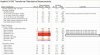
In preparation for my soon-to-arrive parts (tomorrow, if USPS tracking is to be believed), I've started to make measurements. Today took out my ohmmeter and measured the various windings on the power transformer and output transformer for each unit. I've summarized the findings in the following table for anyone who wants to compare their own amplifier to mine. Frankly, I'd love to see these numbers from a known, good working amp. When mine becomes such, I will re-measure as necessary and confirm.

I have no idea what these numbers should be, but I'm comparing the numbers across the two amps. The only possibly concerning variance is in the power transformer, the resistance between the high-voltage to pin 4 of the rectifier tube and the center tap, which is grounded. Amp #1 measures 83 ohms and Amp #2 measures 68. While it's only 15 ohms, on a percentage basis, it's between 18% and 22%, depending on which reading you use as the denominator.

Any thoughts?

Cheers,

Kim G
Boston, MA

Heathkit W-5M transformer measurements.jpg
 
Back
Top Bottom