• The move to the new server is done. There are some software and database maintenance updates in process. This has us passing the hat around to help out. We appreciate any donations. Seriously, even a dollar helps. The payment page may be found here - https://www.audiokarma.org/support.html

Heathkit W-5M Rebuilds

So the good news is that nothing looks shorted. I'm assuming the very low filament windings are close to zero as their low voltage means the windings are short, e.g., not much wire on that winding. Let me know if you believe otherwise. I may take some similar measurements on my Dynaco ST-70 to confirm.

P.S. If anyone wants this table in Excel format, let me know and I'll upload it as a .zip file or otherwise get it to you.
 
Update Time!

My Digikey parts order arrived Friday. I was impressed with their packaging. When you buy a part at Digikey, you can enter a "Customer Reference" text field on each item you purchase. This text is then printed on the sticker on the envelope your part comes in. So if you want to label the "where" of each part as you add it to your cart, Digikey then helps you create a road map for where to put the parts when you get them. Nice feature!

I labeled my parts either "Cap board," or "Heathkit parts replacement." Now I'm wishing I had been more specific.

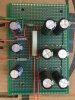
In any case, I've gotten a lot done since my last post. I just finished my first capacitor board, which should be ready for installation. Though I think I'll wait until I've made the second one just so I can compare the construction of the second with the first one. This board essentially recreates the outlined part of the schematic which I posted earlier. It eliminates the need for the can capacitors and also frees up a fair amount of space inside the chassis. I built mine on 4" x 6" through-hole plated perf board. It's designed to be mounted under the power transformer. To mount the board, I replaced the bolts holding the power transformer corners with #8-32 x 1 inch bolts on the corners. I tightened the first nut, then added 3 more to give approximately 12 mm of clearance between the board and the chassis. This seems both more sturdy and easier than using traditional electronics stand-offs. The board thickness plus the tallest caps equals 36 mm. With a roughly 12 mm standoff, this leaves about 6 mm clearance between the tops of the caps and the bottom plate of the chassis, plenty of room. If you build this board, keep in mind that you also need to be able to clear the stud which holds a corner of the tube cage. My setup does that.

IMG_7020.JPG

Making the board wasn't difficult, but it was tedious. The hardest part is drilling the holes precisely as the drill wants to drill through the center of a hole, even if want to start between holes. I used a handheld power drill; a drill press would be better. Initially I was a bit concerned about having sufficient space on the board, so I drilled the holes for the mounting bolts for a tight fit. Unfortunately this made for a difficult-to-install board and I ended up making the holes bigger. Starting off with 1/4" or slightly larger holes would make your job easier. There's plenty of room on the board for the components.

I also initially tried to lay out the board by just plugging in the components and thinking. Ultimately this turned into a dead end, and I broke down and created a layout in a graphics program and then built the board by referring to the diagram. Much easier!

Layout of the Board
Cap Board Layout.jpg

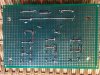
Installing the components wasn't difficult, but running the wiring proved to be tedious, especially as there were many very short jumper wires, which were difficult to neatly plug into the board. I also have a lot of not-beautiful bare wires connecting components on the bottom side of the board. Had I not clipped the leads of the components, I could have used those in several cases. I found that it was nearly impossible to join the holes with bridges of solder -- the fiberglass substrate actively resists solder, as it should.

Top of Board
IMG_7014.JPG
I used red wires for hot wires and green for ground.


Bottom side of board
IMG_7015.JPG
This isn't super-beautiful, but it's electrically sound. The second one should look nicer.

So after I post this, I'm starting work on the second board.

Thanks for all your comments,

Kim G
Boston, MA

Test Fit

IMG_7018.JPG
 
I think that looks great. Nice job.

Thanks! I just finished the second one, which unsurprisingly went much faster. I also did much more of the wiring below the board, and took advantage of the leads from the components. I still have to double-check the second board, but I'm making good progress.

Thanks for stopping by!

Kim
 
The Beast is Alive!

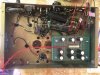
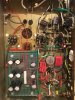
So I managed to replace all of the passive components in one of my W-5Ms. I also installed an 80 ohm NTC thermistor to provide a soft start. I installed the cap board. I reviewed all of my wiring. Everything looked in place, but I was incredibly nervous about plugging it in. First I connected an iPhone to the input jack, and then connected a cheapie beat-box speaker to the output. I started the iPhone with music, and then plugged in the amp. First try, it worked! Sound came through.

IMG_7031.JPG

But....

The amp has a fairly noticeable hum. And I measured the voltages on the tubes. Most were OK, but V1 Pin 1 reads 130 VDC while the spec is 88 volts. Also pin 7 of the same tube measures 128 VDC vs a spec of 88 volts. This might be an issue with my cap board, as these two pins are fed from the same part of the power supply. I'll have to double check.

Anyway, any suggestions as to what to do to correct the hum would be GREATLY APPRECIATED. Should I be using the chassis as a ground? Or should I try to isolate it? There's a ground rail, but it's not clear if the circuit grounds should be connected to the chassis or not. I'll post some more detail tomorrow. Thanks for following along on my build.

Cheers,

Kim G
Boston, MA
 
My suggestions for starters are:
- take each filter cap's negative terminal directly to the circuit's 0V node that it is supplying/bypassing, or to the CT for the input filter cap (ie. don't use a common bus and single link to all those cap grounds).
- only use one link from 0V to chassis (if you disconnect that link then you shouldn't measure low ohms between 0V and chassis.

Then do some basic fault-finding as to which stage the hum is coming from, and what frequency it mainly is.
 
Something's amiss. There should be no voltage difference between V1 pin 1 and pin 7. Make sure the shelf network across 47K/1W to pin 7 is connected correctly.
 
Let me start by saying I know close to zilch about electronics. However, I just came into a pair of beautifully restored W5ms so just thought I’d share this in case it helps.
 

Attachments

  • FE71EE99-A449-4FE4-BB4C-78C9D32BE530.jpeg
    FE71EE99-A449-4FE4-BB4C-78C9D32BE530.jpeg
    74.8 KB · Views: 34
  • 52EF5077-B669-4B76-80DA-CEAE109BFB5B.jpeg
    52EF5077-B669-4B76-80DA-CEAE109BFB5B.jpeg
    66.9 KB · Views: 32
  • 89CF5F0D-2DE0-46E0-9657-3B51D4C815FC.jpeg
    89CF5F0D-2DE0-46E0-9657-3B51D4C815FC.jpeg
    64.4 KB · Views: 32
Something's amiss. There should be no voltage difference between V1 pin 1 and pin 7. Make sure the shelf network across 47K/1W to pin 7 is connected correctly.

You're right; those pins are connected by a wire. The difference is due to me using the 1000 v scale of my VM and having to squint at the needle and then multiply by four, hehe. What I'm wondering is this: if I have new filter caps with lower ESR than the originals, would that cause my PS voltage to run high? Also I increased the capacitance of the last 2 capacitors just beyond the 100 ohm resistor from 20 uF to 47 uF. I'm thinking I've got a problem with over-voltage feeding into pins 7 and 1 of V1 from the PS. And if that's the case, could the hum I'm hearing be caused by that tube operating "too hot" and amplifying what should otherwise be a much quieter-to-imperceptible hum?

I've certainly got some voltage measurement work ahead. Thanks for your help.

Kim
 
My suggestions for starters are:
- take each filter cap's negative terminal directly to the circuit's 0V node that it is supplying/bypassing, or to the CT for the input filter cap (ie. don't use a common bus and single link to all those cap grounds).
- only use one link from 0V to chassis (if you disconnect that link then you shouldn't measure low ohms between 0V and chassis.

Then do some basic fault-finding as to which stage the hum is coming from, and what frequency it mainly is.

Hey Tim!

So I've got my PS filter caps wired up as shown below. The negatives on the filter caps are all wired together and then that bus is tied to the amp's ground rail. (Green wire coming off the board and soldered to the ground wire running the length of the chassis) You are suggesting that I somehow connect each cap's negative terminal to the ground by an additional wire, perhaps only briefly to test the sound?

Any thoughts on my reply to @zackthedog?

Thanks for your input.

Kim
 

Thanks. In fact, I have the original parts list from the manual, and already ordered new components from Digikey. It's only after soldering in all the new components that I've had this thing running. I bought it a couple of weeks ago on eBay from a seller who said it worked. But I never tried it before replacing all the components. So the good news is I was able to replace all the components and it still works. The bad news, of course, is the hum. But I'm getting good suggestions, and today's a new day, so I'm keeping my fingers crossed.

Thanks,

Kim
 
By the way, I'm going to answer a question here for the benefit of later readers which I had going into this. (Which is kind of why I'm documenting this whole process too, to share my experience restoring a pair of these beasts.)

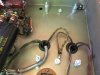
On one leg of the 117 VAC input, I installed an ICL80 NTC 3A 80 ohm thermistor. I was curious how hot it would be in operation. The data sheet says at full power (more than I'm using) it should measure 184° C. Though I don't have a way to measure it, it seems to be about as hot as an output tube. Which is to say that if you install such a thing, you want to give it plenty of clearance and not put it below something that could be damaged by the heat. In my case, if you look at the photo above, it's the thing that looks like a black disc capacitor mounted on a terminal strip near the choke wiring. There it will moderately heat the edge of the choke, but mostly just sheet metal above. I'm glad I didn't mount it near the fuse holder, which is an area full of wires and other plastic things. And I seriously doubt the extra wiring is the cause of my hum as it's far from the input tubes (most sensitive part of the circuit), and also moving the wire while running the amp had zero effect on the hum.

Just FYI
 
OK, hum problem fixed. What I did during the original rebuild process was to connect the ground-lead secondaries of the PT, filament ground and high-voltage ground leads to the chassis. The original build had them connected to the ground bus wire that runs the length of the chassis. When I disconnected these grounds and temporarily connected them with a patch cable to the ground bus the hum became inaudible. Oddly enough, this ground bus is connected to the chassis via the input jack. Anyway, I'm off to measure voltages to see if I can figure out why my V1 has several pins running at excess volts.

Thanks again for everyone's help.
 
Hum level drops when less and less 'external' hum signal mixes in to each stage's ground circuit. The easiest and oldest way for hum to mix in is to use the chassis as the single 0V for all circuitry connections, as the chassis also includes other hum related currents from transformer induction and mains protective earth parasitic currents.

At the the other end of the hum level issue, where hum is pretty low and may not be audibly noticeable, relates to how each B+ filter capacitor is connected throughout the amp. A common ground bus of heavy gauge does a good job at lowering the voltage level of any current loops that mix in to a particular stage's current loop (currents that flow between its parts that connect to 0V). Local staring of each stage's 0V connections to a particular solder blob on the heavy gauge ground bus is an improved way of minimising hum signals caused by the many and various current loops using the ground bus.

Another way to look at this is when someone pays 2-to-10 times the price for an electrolytic capacitor because it has a lower ESR, and then connect that cap to a common bus which can effectively negate any ESR benefit that may have inherently been available.

This is the reasoning behind post #67's suggestions of using individual cap negative leads back to the local star 0V point being used by each stage - in the same manner as you have used individual cap positive leads back to the local star B+ point used by each stage. It's a long held view from back in the 1950's when people started to be more concerned about hum levels, and well known authors like Crowhurst showed the preferred technique.

https://www.dalmura.com.au/static/Pages from Crowhurst Audio Handbook 1.gif
 
Hum level drops when less and less 'external' hum signal mixes in to each stage's ground circuit. The easiest and oldest way for hum to mix in is to use the chassis as the single 0V for all circuitry connections, as the chassis also includes other hum related currents from transformer induction and mains protective earth parasitic currents.

At the the other end of the hum level issue, where hum is pretty low and may not be audibly noticeable, relates to how each B+ filter capacitor is connected throughout the amp. A common ground bus of heavy gauge does a good job at lowering the voltage level of any current loops that mix in to a particular stage's current loop (currents that flow between its parts that connect to 0V). Local staring of each stage's 0V connections to a particular solder blob on the heavy gauge ground bus is an improved way of minimising hum signals caused by the many and various current loops using the ground bus.

Another way to look at this is when someone pays 2-to-10 times the price for an electrolytic capacitor because it has a lower ESR, and then connect that cap to a common bus which can effectively negate any ESR benefit that may have inherently been available.

This is the reasoning behind post #67's suggestions of using individual cap negative leads back to the local star 0V point being used by each stage - in the same manner as you have used individual cap positive leads back to the local star B+ point used by each stage. It's a long held view from back in the 1950's when people started to be more concerned about hum levels, and well known authors like Crowhurst showed the preferred technique.

https://www.dalmura.com.au/static/Pages from Crowhurst Audio Handbook 1.gif

Tim,

Thank you so much. I'm learning a ton from you. I'm working on my next post, which relates to other problems. I'm hoping you might have a pointer or two. Cheers!
 
So with the hum problem fixed, I've turned my attention to the voltage problem. Basically, V1 pin 1 runs at 130 volts but spec is 88, so it's 48% over, a bit too much to ignore. The Heathkit manual says if you're within 20%, you are fine. Pin 7 has the same spec and the same problem. Pin 8 runs at 130 volts but spec is 100.

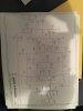
So I checked the voltages off the power supply, which in this case is basically my cap board. Despite the proper spec of resistors, it's putting out way too much voltage to V1 and V2. This makes me wonder if these resistors were properly specified in the first place. See the diagram below which makes things clearer.

Input voltage from pin 2 of the rectifier measures 520 v vs spec of 510, so that's fine.
On my board, the power takeoff point which corresponds to capacitor "G", half-circle lug, the spec is 350 V, but I'm getting 412 V. This goes to V1 Pin 7, via 47K resistor, which is wired on the chassis/terminal strip.
Also, the power takeoff point which corresponds to capacitor "G" square lug, the spec is 400 V, but the board is putting out 468 V. This goes to V2 Pin 1 and Pin 6, via a pair of matched 47K ohm resistors.
Oddly, the power takeoff point which corresponds to capacitor "G" triangle lug is putting out 360V vs spec at 380V. That one is fine.

The Problem
With the hum fixed, the amp sounds crappy. It sounds like it's clipping at more than very soft volume. If you turn it up, it sounds very distorted, kind of like the sound you get right after you turn off the amp, but before the capacitors discharge.

I tried putting some additional resistors between the cap board and where the power goes in order to drop the voltage closer to spec. Oddly enough, this made the problem worse. Maybe because I upset the voltage balance between different sections of the tube? I have no idea. It struck me as a very strange result.

I also tried swapping tubes with the other amplifier, but that did nothing.

Oh, and when the amp starts up, the first few seconds after you can hear the source, there's a sort of popping/breaking up noise before the amp fully warms up.

I've pretty carefully checked my solder joints. I've been very careful to put everything into the right places. I'm at a bit of a loss.

One thing I'm wondering is if I may have selected inappropriate filter capacitors for my cap board. They are slightly higher mfd than spec (47 vs 40 spec, and 22 vs 20 spec), but that doesn't seem like it should matter. When the amp is running, they seem to warm up, which strikes me as odd.

So I'm at a bit of a loss. Any suggestions would be VERY welcome. FYI I have an old oscilloscope which can be brought to bear if necessary.

Thanks to everyone for their help.

Kim G
Boston, MA
Where some people do crossword puzzles and some rebuild amplifiers.
Cap Board with Voltage Variances.jpg
 
There's nothing wrong with your filter caps. The amp sounds crappy because the V1 is out of whack, maybe more. Go through and check all your connections to the V1 and V2 pins, make sure they are correct. I'll keep staring at this and see if I can see anything. ;-)
 
There's nothing wrong with your filter caps. The amp sounds crappy because the V1 is out of whack, maybe more. Go through and check all your connections to the V1 and V2 pins, make sure they are correct. I'll keep staring at this and see if I can see anything. ;-)

OK, I did some browsing here on AK looking for people with similar problems. One poster suggested that one should check that the OPT common was indeed connected to ground. Well, I just plugged the amp back in and connected a jumper wire between the ground rail and the common terminal on the secondary side of the OPT, and voila! The amp sounds terrific. Not only that, but with my ear pressed up against the speaker, it's dead quiet. I'm driving it with my iPhone with no preamp, and it doesn't get that loud, but I'm hoping it'll do more when connected to my preamp and main speakers. (I'm currently testing on a crappy pair of Infinity Reference 2000.4 which aren't that efficient.)

I'm thinking now that I should revisit the resistor problem and get the voltages where they should be. Then I should have attained my goal: a terrific-sounding tube amp.

Cheers,

Kim G
 
Last edited:
Back
Top Bottom