• The move to the new server is done. There are some software and database maintenance updates in process. This has us passing the hat around to help out. We appreciate any donations. Seriously, even a dollar helps. The payment page may be found here - https://www.audiokarma.org/support.html

Heathkit W-5M Rebuilds

I would love to take you up on that as soon as this virus nightmare is over! ;-). And I'd like to hear those W5's. A friend gave me two that his grandfather owned but they were completely blown and I passed them along, but not before getting them into some kind of shape and sensing that they were special. Since then I've acquired a stash of 16309 outputs and plan to build a fresh pair from scratch. One of my audio gurus was a big fan of the Mullard 5-20 circuit until he heard a pair of W5's and did a complete about-face. It's now his favorite circuit. I would not be alone in considering the 12AU7 to be a poor sister in the tube department, but Heathkit really worked some magic with the W5.

I'm listening to what is commonly known as the "Musician's Amplifier," the first American version of the British Williamson. You'll find the documentation on Tim's site:

http://oestex.com/tubes/mus_amp .pdf

Instead of the original Partridge OPT, it used a Peerless S-265-Q, a truly magnificent transformer. Heathkit subsequently co-opted the design for the W2, then upgraded that with an Acrosound transformer for the W3, and finally cheaped out a bit with the W4. I've gotten lazy in my old age and simply cobbled a pair of S-265-Q's onto some salvaged W4 chassis. Heresy, I know but it worked out fine
 
It can save some grief every now and then by taking the time to do redundant checking - such as get the 470R resistor out of the 470R bin and confirm it is 470R with a DVM - then after it is installed do another check with DVM (preferably from other nodes in the circuit). We've all been caught out by the cuckoo resistor that is in the wrong bin masquerading with pretty much the correct colour bands, or soldering it in only to realise it or another solder joint was NQR. And the same goes with checking cathode and anode voltages on valves, and tube rolling with valve rocking in sockets to confirm the stage's operation is robust with no intermittent operation.
 
It can save some grief every now and then by taking the time to do redundant checking - such as get the 470R resistor out of the 470R bin and confirm it is 470R with a DVM - then after it is installed do another check with DVM (preferably from other nodes in the circuit). We've all been caught out by the cuckoo resistor that is in the wrong bin masquerading with pretty much the correct colour bands, or soldering it in only to realise it or another solder joint was NQR. And the same goes with checking cathode and anode voltages on valves, and tube rolling with valve rocking in sockets to confirm the stage's operation is robust with no intermittent operation.

Tim, you are so right. And honestly, with the tiny half-watt resistors these days, it's very very hard to read the color bands. Frankly, if I were Czar of the World, I'd have the number printed onto the resistor. Worse, as you'll see below, my ohm meter isn't exactly precision.

But I just measured V1P3 to ground and it comes out around 550 ohms, but my ohmmeter tends to read high, as the other resistor for the other amp measures 620-ish. If I do the math of the 470 (cathode to ground resistor) and the 4700 ohm (NFB between P3 and ground) resistors in parallel should be 427 ohms. That's probably close to what my crappy ohm meter is getting, but It's becoming clear I need a better meter.

Thanks for you help,

Kim
 
@zackthedog Well, you are vindicated! New tubes changed the voltages, though I still have one concern.

I took some Sylvania 6189s out of my Dynaco which are basically NOS mil-spec 12AU7s and dropped them into the W-5M and retested. These tubes should be very good as I got them in October, so only about 6 months of use. First, the voltages off the cap board, which correspond to the capacitor "G" on the schematic, fell right into line, with only G half circle being 360V vs spec of 350V, or essentially in line with spec.

Two, I remeasured the voltages on V1 and V2. But before going into the details, I should add that I have realized the inaccuracy of my cheap, 1980's Radio Shack/Micronta VM. It has various ways to measure voltage, including two input jacks for the positive lead, and then a V/2 switch. If I measure the same voltage using different variations of these input jacks and the switch, I get variations in measurements of around 5%, perhaps a smidgen more. I also recalibrated the dial by using a fresh AA battery and set the needle (via the adjustment screw on the face) to measure 1.56 V. Still, I'm dealing with an instrument that's not too precise. It may be good enough for the job, but I'm thinking of upgrading what I have. As an aside do you think I can get a good meter for $50-ish? $100-ish? Any thoughts are appreciated.

So, V1P1 now measures about 106V vs spec of 88, or 20% above, just at the edge of spec. Ditto for pin 7 which is connected to P1 with a wire. Pin 3 measure 2.4 vs 2.2 spec, or 9% over, which is OK. P6 measures 230 vs spec of 280, 18% below, technically OK. What's interesting about this is that it came down a bit with the new tubes, but the part of the power supply that feeds it came up 20V. So go figure. Maybe the new tube is drawing less current? So what do you think I should do with that V1P1? Just live with the high-ish voltage?

As for V2, P1 now at 266 vs spec at 255, which is OK. P6 reads 263V vs spec at 255V, so it's fine too.

V1P3 to ground measures 550 ohms, but my vm tends to read high. I just measured the 470 ohm resistor that is supposed to go into the other amp, and it measures around 620. Since its a Vishay 2% resistor, I'm going to chalk up the variance to the inaccuracy of my meter. I know it doesn't work this way, at least at large scale, but if we simply take the 150 ohm error from the resistor measurement and apply it to the V1P3 to ground gets us to 400 ohms, not far off the 330 you suggested it should be. Please let me know if this is "wrongthink." I calculate that the resistance should be 427 ohms if you do the math on the 470 ohm cathode resistor and 4.7K ohm NFB resistors in parallel.

Though I wasn't listening too critically, I think the amp did sound better with the 6189s instead of the Mullard, but it wasn't dramatic.

Anyway, for now, I'm thinking the first amp is running more-or-less acceptably, save perhaps for that V1P1/P7 over-voltage. Let me know what you all think. I'm going to get back to work replacing components on amplifier #2.

So where are you located? I'd be thrilled to buy you a beer and/or show you my W-5Ms any time you want. @trobbins, you too, but you're almost impossibly far away.

Thanks to you both,

Kim G
 
Nowadays there are quite a few cheap 4-digit small DMM's with lots of functions and very accurate - I have two Aneng AN8009 - cheap DMM's like these are not for measuring mains AC as they are not proper CAT rated, but with care and not being too heavy-handed with them then they can be great for amp servicing - the test leads are usually a downside too.
 
Well, I'm glad it worked out, mostly because you put a lot of work into it and did a very nice job refurbishing it.

I would definitely get a digital multimeter. Be sure to get one that measures up to 1000vdc. These cost around $70 at Home Depot, or online or wherever it's convenient to get one. I think your working with a very inaccurate one now. I suspect that the resistance from V1/pin 3 is probably correct, your meter is just out of spec. But once you get a new meter I would check it again.

Also, for my peace of mind, and with a fresh tube in that position, please check V2/pin 3 and also the voltage at the G/square to make sure you're not running that cap close to the edge. It would also be good to know the cathode and plate voltages of 5881. The W5 runs them a bit hard and you want to be careful not to exceed the 25 watt rating of the 5881s.

The voltages you're getting now are fairly in line with over-voltage from the power transformer. The filament voltages are also likely a bit too high. In the long run it would be best to get filament and HV voltages down to spec levels. I have found that a .1 ohm, 5 watt resistor in series with one leg of the 6.3 volt supply will bring the filament voltages down to a comfortable level. In terms of the main HV, you can put a pair of 100 ohm, 10 watt resistor in series with each plate of the 5R4 (pins 4 and 6) and that will bring the main HV more in line with spec and be kinder to your output tubes.

I'm in Oregon so it may be a while before I can have that beer, but we're overdue for a trip back east when this virus thing settles down, so who knows? ;-)
 
@zackthedog, @trobbins, @Pio1980

Hey Folks,

It has been quite a while since I've updated this thread. About 5 weeks ago, I received NOS 12AU7s and some new KT66s for each amplifier. Initially, they sounded very good, and after some burn-in, they sound amazing. I've been in audio bliss for a while now.

But....

The right channel amplifier used to emit (though the speakers) a sort of Pfffftt sound about 7 seconds after power up. Then it worked fine. This annoyed me a little, but I figured I could live with it. Well, over the ensuing weeks, that amplifier has developed some low-level noise. That noise sounds much like the sound of a record player after the music is done and it's running in the blank groove at the end. Often it takes about 20 minutes of running the amp before the noise sets in, but once it's there, it doesn't stop. This noise is NOT a hum. It's random, slightly scratchy, slightly poppy, and only noticeable between tracks or in low-level passages of classical music. If I listened only to rock, I'd probably not notice it. But since I listen to a ton of classical music, it's very annoying.

Today I put the amp on the bench and started to look for faults. (By the way, since I last wrote, I bought a new DVM, a Klein Tools MM600, so my measurements are more reliable.) First, I swapped all the signal tubes with the other amp. This made no difference, which is not surprising as all the tubes are new. The Heathkit manual suggests that noise could be a bad resistor or a bad soldering job. Since almost all the resistors are new (I kept the old wire-wound resistors, but replaced everything else), a bad resistor seems unlikely. But I did look closely at my solder joints and re-flowed a couple of them. No change. However, I noticed that the 47K ohm resistor which sits between the power supply (capacitor G half-circle) and V1 P7&P1 (plates of the two sides of V1 a 12AU7) looked like it had been hot. I measured its temperature and it was running at 117°C. If I'm reading the data sheet correctly, it should be fine up to 155° C, and it has a rated operating voltage of 500 V. In any case, I temporarily swapped the old resistor back into its place, but that made no difference to the noise. However, the old resistor quickly got hot too. This is a 1 watt resistor and I'm wondering if it'd be smart to replace it with a 2W resistor. By the way, this resistor is seeing about 107 VDC when it really should be seeing closer to 88. Some of the other resistors also seem over-warm to me, but I'm not experienced enough to know how normal this is. The other resistors are much cooler than the one mentioned, but I did not measure their temperatures.

As a side note, even with new tubes, the over-voltage problems I had earlier are still there more or less. A smidgen might be line voltage as my house current measures 123 VAC today, which is about 7% higher than the old standard of 115VAC. Interestingly, I think I may have a bad rectifier tube as it puts out 466 VDC on pin 2. I swapped it with the rectifier from the other amp, which puts out 509 VDC. The swap made no impact on the noise. I guess I'll get another rectifier tube, but I always thought that rectifiers were pretty much either functional or dead. In any case, aside from the weirdness of having a low-output rectifier combined with over-voltages elsewhere, I don't think this is the problem as the amp sounded the same with either rectifier tube. And the other amp has the same over-voltages, mainly on V1, but I'll consider that a problem for another day.

To troubleshoot noise problems, the Heathkit manual suggested removing tubes, one at a time, and powering up to see if the sound would go away. So starting with V1, I removed tubes. Without V1, there's no noise, though there is a little hum without V1. So I measured the resistors around V1, but all were on spec. I also measured the resistance between pin 3 of V1 and ground with V1 removed and got a figure of 427 ohms, which seems about right. There's a 470 ohm resistor from V1 P3 to ground plus a 4.7K ohm resistor that connects to V1 P3 and is grounded on the other end via the secondary winding of the OPT. So based on my calculations, the 427 ohms resistance is pretty much on the money. And since removing V1 got rid of the noise, I didn't repeat the experiment with other tubes.

I also "chopsticked" the amp, basically poking and prodding solder joints, tube pins, wires, etc, while running the amp. Nothing changed the sound of the noise, so I'm tending to rule out more bad solder joints. And reflowing the questionable ones didn't make any difference. While I suppose it's possible I've gotten a bad resistor, it seems unlikely. I ordered low-tolerance, metal-film resistors (1% mostly). And the electronics industry seems to have quality control down to a very precise science these days.

So I'm at a bit of a loss as to what my next step should be. I have a cranky, old, Textronix oscilloscope which could be brought to bear. But frankly, I don't really know how to use it beyond the most basic idea of tapping into the signal path at various points to see what I can see. My main concern is not blowing up the scope via tapping into something at an intolerably high voltage.

Anyway, I remain indebted to those of you who have helped along the way, and any suggestions about how to solve my noise problem are very much welcome.

Thank you,

Kim G
Boston, MA
Where a stay-at-home advisory has given plenty of time for projects.

P.S. I'm wondering if my over-voltages could be due to the fact that I rebuilt this amp with a capacitor board with modern, low ESR capacitors that replaced the old can capacitor, which presumably has higher ESR. Thoughts?

 
From the manual chart, feed voltage is 350V, and triode has 88V on plate/grid, so 47k plate feed should have circa 350-88 = 262V across it. The current through that 47k should be circa 2.2V/470 = 4.7mA, which would cause a nominal 4.7mA x 47k = 220V drop, with a 1W dissipation. There will be some tolerance due to the resolution of the chart values, and resistor tolerances, so actual measured voltages will likely not exactly align. If you have 107V on the plate then that may be ok. And yes a 2W resistor would be much more appropriate if it was dissipating 1W.

The noise that starts after a few minutes would indicate it is related to a part or contact coming up in temperature from ambient. Apart from solder joints, the valve base contact with valve pins could also be a concern, so some contact cleaner may be worthwhile applying. The other test to use is a spray can of 'air duster' or contact cleaner - and using a thin tube extension nozel, to spray a small amount on each suspect part so as to rapidly cool it - for the air duster can, it is typically upended so that some of the flourocarbon liquid gets squirted out, which then rapidly evaporates on the part and freeze chills it.
 
@trobbins

Hi Tim,

Thanks for the suggestions. I have wiggled the tubes while the amp is running, but that produced absolutely no change in the noise, nor in its randomness. I'm quite puzzled. That said, would you recommend spraying the tube sockets with DeOxit? Can I reasonably assume that the noise is coming from something in close proximity to V1 since the noise disappeared when I removed it?

Thanks so much for your help. I really appreciate it.

Have a great day,

Kim
 
Update:

Before the below, I sprayed Deoxit into the sockets for V1 and V2 and did my best to clean the pin sockets with a paper clip. I'd also note that the noise is now coming on pretty much as soon as the amp will play music, e.g., essentially immediately.

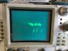
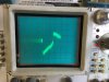
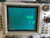
Figuring that a picture is worth a thousand words, I decided to connect my oscilloscope to the speaker outputs and take some photos of the noise. It appears that the signal is showing a random voltage fluctuation and intermittent cut-outs. At least that's what I'm taking away from the photos, which I'm posting below. There was no signal or music being played through the amp while the photos were taken.

The oscilloscope is a Textronix 465M,which is a military version of the 465. I'm using a 10:1 probe with a 1 M ohm /12 pf input. The vertical scale is 50 mv and the time base is 10 milliseconds.

Oscillograms/Photos below:
IMG_7263.JPG IMG_7265.JPG IMG_7266.JPG
 
Well, this is a devilish problem. As with Tim's reply, common sense would indicate a loose solder joint or bad resistor, and it's a good idea to never assume that even new resistors are good. It's also a good idea to overrate resistors in critical positions, especially plate resistors. You might try a 2W resistor on the plate of the V1 and see if the overheating is causing the problem.

It's *also* possible that as the tubes warm up and reach a certain level of transconductance, the amp is oscillating for some reason. Try disconnecting the negative feedback and see if it still makes the noise. That will tell us something.

I'm still skeptical of that 427 ohm resistance from the cathode of V1 to ground. It should be lower, IMO. Measure the same thing on the other amp and see if it's the same.

You said you swapped the "signal tubes'--did you swap the KT66's? Could be a bad grid in one of those, but if the noise disappears with V1 removed that would seem unlikely.

Check everything around V1 again, both sections, measuring all resistors, including the decoupling resistors in the power supply. There also might be a problem with a decoupling capacitor arcing intermittently.

Also measure all plate voltages on V1 and V2 and make sure they are withing range. If the two plates of V2 are way out of balance, like 20-30 volts, that's a sign of oscillation.

Keep at it, the answer will appear. Unless it's a bad output transformer, which is highly unlikely, the rest is all fixable.
 
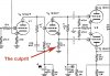
OK, I may have solved this problem. I was reading through a thread from another guy who had a W-5M and had done what I did -- replace all the passive components -- and he had the same problem. In his case, it turned out to be a 22K resistor on V1P6. This resistor is one of a matched pair, the other one attaching to V1P8. So I decided to measure this pair of resistors. Well, one measured 22.15 K ohm and the other one measured 22.03K ohm. As it turns out, I had bought extras of all the resistors that needed to be matched so that I could find the best matched pairs. So I had two extras, and they both measured 22.15K ohms on the nose. So I replaced the 22.03K and voila! So far the amp has been running for about a half hour and it's dead quiet. Like dead quiet as in I can put my ear up to the speaker when the CD is on pause and I can't even tell the thing is running. Which is how the other amp sounds. And this amp now sounds sweeter and clearer.

@zackthedog -- It looks like we were both writing at the same time. I've been working on this thing all day, hehe. I TOTALLY 100% APPRECIATE your help. And yes, I switched the KT66 tubes when I switched the other ones. Though the 12AU7s are NOS, the KT66s are brand new Gold Lions. Initially I did not swap the rectifiers, but tried that yesterday which is when I discovered I had a weak one. I need to buy a new one. Do you think I should buy two so the two amps are still matched? Or does it not matter?

Bad Resistor W-5M Schematic.jpg
 
OK, I may have solved this problem. I was reading through a thread from another guy who had a W-5M and had done what I did -- replace all the passive components -- and he had the same problem. In his case, it turned out to be a 22K resistor on V1P6. This resistor is one of a matched pair, the other one attaching to V1P8. So I decided to measure this pair of resistors. Well, one measured 22.15 K ohm and the other one measured 22.03K ohm. As it turns out, I had bought extras of all the resistors that needed to be matched so that I could find the best matched pairs. So I had two extras, and they both measured 22.15K ohms on the nose. So I replaced the 22.03K and voila! So far the amp has been running for about a half hour and it's dead quiet. Like dead quiet as in I can put my ear up to the speaker when the CD is on pause and I can't even tell the thing is running. Which is how the other amp sounds. And this amp now sounds sweeter and clearer.

@zackthedog -- It looks like we were both writing at the same time. I've been working on this thing all day, hehe. I TOTALLY 100% APPRECIATE your help. And yes, I switched the KT66 tubes when I switched the other ones. Though the 12AU7s are NOS, the KT66s are brand new Gold Lions. Initially I did not swap the rectifiers, but tried that yesterday which is when I discovered I had a weak one. I need to buy a new one. Do you think I should buy two so the two amps are still matched? Or does it not matter?

View attachment 1919888

Well, honestly, that small a differeence shouldn't have caused any problems. I think you probably rectified some other problem or found a noisy resistor in the process, but at any rate I'm glad the problem is solved!
 
Oh, I totally agree about the difference in values. But I think the resistor had gone bad/noisy and the difference in value was the only clue. Visually it looked brand new. If this happens again, I'm just going to remeasure everything, and with my new DVM, I think I can rely more on the measurements. Thanks again! Cheers, Kim
 
Oh, I totally agree about the difference in values. But I think the resistor had gone bad/noisy and the difference in value was the only clue. Visually it looked brand new. If this happens again, I'm just going to remeasure everything, and with my new DVM, I think I can rely more on the measurements. Thanks again! Cheers, Kim

Fair enough, and very glad you're up and running again.
 
Initially I did not swap the rectifiers, but tried that yesterday which is when I discovered I had a weak one.
There is a chance that this was the root cause. Not sure on your timing of when parts were swapped out, but rectifier arcing can initially be minor and ad hoc.

I would always recommend any amp with a valve rectifier to have the 'ss diode in series with valve diode anode' modification, simply because the valve diode is somewhat similar to an output stage valve in that it will age in a much shorter time frame than any other valve part, and has the capability of taking the PT as collateral damage. It is a surreptitious modification in that it doesn't change the operating behaviour of the amp, but it does require wiring in parts with some care, so is not a 'beginner' mod per se. It also practically avoids the need for a spare valve to be at hand.
 
Hi Tim,

I replaced the audio valves about 6 weeks ago, and the passive components were replaced in April, more or less. But I didn't replace either rectifier as they appeared to be working.

I've seen various diagrams of putting silicon diodes between the rectifier tube and the downstream components, if I recall correctly. Or maybe it's diodes upstream of the valve rectifier. But it's never been totally clear to me how this is installed. Is the idea to "pre-rectify" the a/c with the diodes and then pass the DC through the valve in order to get the proper voltage drop? And I guess this also prevents some kind of electrical kickback into the PT under certain circumstances?

I'd love to do this. In fact, I ordered enough silicon diodes with 1,000 volt rating to do it. I just need a little clarity on where to put the diodes.

In any case, thanks for following along my thread and all of the help. The papers you wrote and recommended to me were helpful as were your comment. I am 100% GRATEFUL for your help.

Thanks,

Kim
 
The added ss 'diode' takes over the role of supporting the inverse voltage for the diode anode that is not conducting - and eliminates any chance of reverse leakage current through the valve diode causing an internal arc (which is a not a too uncommon failure mode of rectifier valves). An example schematic of where that 'diode' connects in is shown in linked sketch by Willabe from el34world.com.
index.php


As the secondary voltage is quite high at 455VAC, it would be appropriate to use 3x 1N4007 in series for each 'diode' connecting to a 5AR4 anode. Those ss diodes should be from the same batch, and should have their leads soldered directly to each other so that all three diodes have the same internal junction temperature - that plus the voltage margin of using 3 in series, and the mains frequency application, means that there is no need for any static or dynamic balancing parts across the diodes (extra balancing parts are sometimes seen in schematics or recommended on forums).

Don’t be tempted to connect anything to the typically unused pins 3, 5, and 7, on a rectifier valve socket, as pins 2 and 4 can have a very high inverse voltage at the anode, which has the risk of causing arc tracks to the neighbouring pin. Keep the valve socket clean around pins 4 and 6 (eg. by wiping with meths or IPA using a cotton bud), to avoid any pollution residue from assisting an arc to form. Do not mount any supporting ss diodes to pins 3, 5, 7 as that similarly increases the risk of arcing – preferably add in a small terminal strip located so as to making the wiring short and convenient. If you scour the internet, schematics and sketches often show this mod with diodes connecting to pins 3, 5 or 7, and although that may be convenient for many amps, the 455-0-455V secondary of the W5M is starting to get up in voltage and so is a risk.
 
Hi Tim,

So yes, this mod essentially "pre-rectifies" the current, and prevents any current from going back into the PT, all of which makes perfect sense. As part of my overall parts order, I purchased six diodes, with the idea that I'd put two in each of my W-5Ms and two into my ST-70. The diodes are UF4007 TR diodes (DIODE GEN PURP 1000V 1A DO41) which are rated to a max reverse voltage of 1000 volts and a current carrying capacity of 1 amp. I was thinking that since the voltage rating is more than double the 455 volts at each leg that one diode per leg should be enough. And my schematic indicates that the secondary circuit of the PT puts out 140 ma, well below a single diode's rating. So why do you recommend three diodes per leg? I'm asking more to learn than anything else.

Thanks again,

Kim
 
There is some discussion on series connection of ss diodes in linked technical article below - it relates to what PIV safety margins you may apply, both for the peak reverse voltage experienced in your power supply, and what peak reverse voltage rating is appropriate when connecting diodes in series.

This technique is a sort of a hybrid rectifier, in that it uses certain attributes of valve and ss diodes to gain a better outcome for the user. Akin to placing a damper diode in the B+ feed from a ss bridge rectifier to provide a 'slow start' rectifier benefit.

https://www.dalmura.com.au/static/Power supply issues for tube amps.pdf
 
Back
Top Bottom