• The move to the new server is done. There are some software and database maintenance updates in process. This has us passing the hat around to help out. We appreciate any donations. Seriously, even a dollar helps. The payment page may be found here - https://www.audiokarma.org/support.html

Heathkit W-5M Rebuilds

So are you saying you hadn't connected the OPT secondary winding to gnd, as per the amp schematic?

If an early stage is not passing nominal current then its feed B+ level will be high. For example the input stage should have a cathode voltage of about 2V - if it is lower then less anode current is flowing and anode voltage will be higher, and feed B+ will be higher. If you have tube swapped and no change, then confirm the resistor values for 470R and 47k, and perhaps even disconnect the 2nd stage grid to confirm it isn't influencing the first stage.
 
So are you saying you hadn't connected the OPT secondary winding to gnd, as per the amp schematic?

If an early stage is not passing nominal current then its feed B+ level will be high. For example the input stage should have a cathode voltage of about 2V - if it is lower then less anode current is flowing and anode voltage will be higher, and feed B+ will be higher. If you have tube swapped and no change, then confirm the resistor values for 470R and 47k, and perhaps even disconnect the 2nd stage grid to confirm it isn't influencing the first stage.


Hi Tim,

Yes, indeed! I hadn't connected the OPT secondary winding to ground as indicated. I don't think it was connected when I got the amp as I was VERY careful to replace parts one-by-one. As far as I can tell, the amp came to me that way, and the other one (which I have mostly not touched) also appears to be that way. So connecting that has made a HUGE difference. I'm assuming because the NFB circuit now can work properly. In fact, the output level is lower with the ground connected, but the sound is 1000% better.

I'm going to order some new resistors from Digikey. My plan is to replace the 6.8K on the cap board with a 15K or maybe a 16K. With 15k, that resistor will create a voltage out of 412 for a use which specs at 400 V. If I can get it closer to 400 V with the 16K ohm resistor, I'll do it. I'm also going to replace the 15K ohm resistor with a 22K which should produce 360V, close enough to 350V spec. I'll also try a 16K to see if I can get to 350V dead-on.

Given that my input voltage to the cap board is more or less on-spec at 520 V (vs spec of 510), I'm wondering if this is an error on Heathkit's part. In any case, I'm now very close to having a pair of very nice sounding W-5Ms.

Do you think that the over-voltages might have damaged V1?

Thanks for all your help. You've taught me some very useful things.

Cheers,

Kim
 
No, wait, wait, wait! Do not replace resistor values. The circuit should work as designed. If it doesn't you need to find out why. It's unlikely anything has been damaged. You need to track down the source of the voltages discrepancies.
 
No, wait, wait, wait! Do not replace resistor values. The circuit should work as designed. If it doesn't you need to find out why. It's unlikely anything has been damaged. You need to track down the source of the voltages discrepancies.

I will re-measure, but at this point I can only conclude that those dropping resistors in the power supply are the culprit. Upstream voltage is fine, the output is way over spec as I demonstrated a couple of posts back, (see post #72, the one with the diagram and the variances highlighted in yellow), and it's feeding into circuits where the voltage variance pretty closely tracks the variance at the power supply.

I understand your reluctance to declare a design fault, but let's assume at least for purposes of discussion that I have indeed measured correctly, what else could it be? There's not much more to the circuit than what I've just described.

Again, I haven't yet remeasured the voltages with the OPT ground connected, and maybe the voltage will "sag" back to spec. But I did spend some time listening to the amp with the problem fixed. Man! It sounds sweet, very quiet, very detailed. I'm dying to finish the second one and hook them up to my system.
 
As Tim has mentioned, check *all* voltages on the manual's chart, including cathode voltages. Glad it sounds good! But it will sound even better if we can find the source of the problem. :-)
 
As Tim has mentioned, check *all* voltages on the manual's chart, including cathode voltages. Glad it sounds good! But it will sound even better if we can find the source of the problem. :)

There's a chart on page 25 of the Heathkit manual. I checked all the voltages mentioned, and all were more or less in spec, except those discussed. But I will re-check. Also, I don't know if you are familiar with Chimera Labs and its proposed modifications to the basic Williamson amplifier design, but it discusses the fact that there were some errors in that design that got made into amplifiers before being corrected. So it's possible those resistors are simply wrong. But again, I'll remeasure.

Oh, and here's an additional point supporting the error thesis. If you look at my diagram on post #72, you'll note that the top capacitor on the right, which is coupled with a 22K ohm resistor has a higher voltage spec than the bottom capacitor which is coupled with a 15K ohm resistor. Simply swapping those two would bring the amp closer to the specified voltages. Right? The top one is supposed to put out a higher voltage than the bottom one, yet the top one goes through a bigger resistor, e.g., is "supposed" to have more voltage drop.

It doesn't seem completely crazy that there could be a mistake in the schematic, particularly if the amp sounds so nice despite that mistake. In any case, I'll remeasure today. Meanwhile Digikey is going to send me an assortment of slightly different resistors that I can plug in to correct the problem if my thesis is correct.

Thanks again for all your help.

Have a great day,

Kim
 
The Chimera Labs mods have been discussed here before and there's little enthusiasm for them from people familiar with the Williamson. If there were errors in the original schematic, Sheldon wouldn't have designed his power supply board to conform to it. Folks have been building, repairing and rebuilding W5s for 70 years based on the manual. ;-)

Now that you have the feedback circuit working properly, you should take new measurements. Also, what tubes are you using? Are they new, used, whatever came with the amps? You might try swapping some different 12AU7s in to see if the voltages come into line.
 
The Chimera Labs mods have been discussed here before and there's little enthusiasm for them from people familiar with the Williamson. If there were errors in the original schematic, Sheldon wouldn't have designed his power supply board to conform to it. Folks have been building, repairing and rebuilding W5s for 70 years based on the manual. ;-)

Now that you have the feedback circuit working properly, you should take new measurements. Also, what tubes are you using? Are they new, used, whatever came with the amps? You might try swapping some different 12AU7s in to see if the voltages come into line.


I did remeasure today. With the ground wire attached to the output transformer, the V1 Pin 6 voltage (from capacitor "G, triangle") is the same, 360 V vs 380 spec, or 5% under. According to the Heathkit manual, anything within 20% is in spec, so that's in spec.

The "G Square" capacitor voltage is 448, 12% over the 400 V spec, so technically within spec, but I'm going to try to get it lower via a resistor that's greater than 6.8 K ohm.

And G Half Circle voltage is 400 V, 14% over the 350 V spec, again technically OK. But since the only purpose of the resistors in this part of the power supply is to drop voltage to various parts of the circuit, I can see no reason to not put a higher-rated resistor and get closer to spec. If nothing else, this should conserve tube life. I've already got an assortment of resistors around these values on the way from Digikey.

As for Chimera Labs, I re-read the document I found. It was less Heathkit-specific than I remember, so I'm inclined to ignore it for now, especially as the one amp I have running sounds very nice.

For tubes, I've got 4 (2 per amp) Mullard 12AU7 tubes that have "made in England" stamped on them. I presume these are desirable tubes. For the output tubes, I have a pair of Tung Sol 5881s, which @Pio1980 says are very nice if good, and they seem to be good. And the rectifiers are old RCA "made in America" Radiotron Electron Tubes, 5R4GY. One of them has what looks like small white paint flecks inside. I'm hoping that doesn't affect the function. After I tapped the glass with a fingernail, the flakes fell to the bottom of the tube.

Since I last wrote, I've connected the amp to my main stereo and speaker. When I played music through it, I got goosebumps. The sound is amazing. There's absolutely zero noise. If I press my ear against the speaker I can hear only the very faintest hint of some kind of hiss. More than 2" from the speaker and it's completely inaudible. The bass is extended well beyond what my Dynaco ST-70 produces. (And that was improved significantly with the VTA input board.) Vocals are incredibly present, and the overall presentation of sound is lively, and even with only one speaker, surprisingly holographic. I can hardly wait to get the second amp running. I think they're going to be incredible.

When all is said and done, I will have about $1,000 into this pair of amplifiers, and I'd say they can hold their own with some of the best. I'm very happy, and will be twice as happy when I get the second one running.

Thanks for your help.

Cheers,

Kim
 
P.S. @zackthedog
The amp was designed for KT66 tubes. I'm wondering if you think it'd sound better with some new-production version of those. I'm thinking maybe the Genelex Gold Lions which seem to have good reviews on tubedepot.com. That said, it seems like this tube is somewhat unusual. I'm wondering if that means I should stock up. The Gold Lions are about $43 each, and I'd need 4 for a set. Not exactly free, but they should last for years too. Thoughts?
 
P.P.S. This amplifier definitely runs warm. I've been running mine most of the day and I just went to check it out. The power transformer is so hot that I can only put my hand on it for about 4 seconds before I have to pull away. And the OPT and the choke are also quite warm, but not as warm as the PT. This amp seems to run hotter than my Dynaco ST-70. Thank God it's got a nice tube cage.
 
P.P.S. This amplifier definitely runs warm. I've been running mine most of the day and I just went to check it out. The power transformer is so hot that I can only put my hand on it for about 4 seconds before I have to pull away. And the OPT and the choke are also quite warm, but not as warm as the PT. This amp seems to run hotter than my Dynaco ST-70. Thank God it's got a nice tube cage.
The cage will run it hotter.
 
What would really be helpful in diagnosing the wayward voltages is if you could measure the voltage readings at the actual tube socket pins, not at the power capacitors. Specifically, it would be useful to know the voltage measured from V1 pin 3 to ground (should be 2.2vdc), and from V2 pin 3 or 8 to ground (should be 13vdc). "More or less" isn't good enough here, these voltages need to be *very* close to what the chart indicates, within .2 volts or less. Also, please check the voltage from each test point for the output tubes to ground (should be about 50vdc). I suspect what is happening is that both 12AU7s are worn and not operating properly. You're dropping too much voltage across the 22K resistor because the second stage of V1 has 130 volts on its grid instead of 88, which is causing it to draw way too much current. I would strongly urge you, before changing any resistors, to check these voltages, which will tell us a good deal about the tubes themselves--and also to beg, borrow, buy or steal a fresh pair of 12AU7s to test in the amp. At the very least, try swapping out the pair from the other amp.

The power transformers are underspec'd and will normally run hot, but checking the voltage from the output tube test points to ground will also tell us if they are drawing too much current and possibly putting a strain on the power transformer. You'd be best off to remove the cages during operation, as Pio1980 mentions.

The Mullard 12AU7s are indeed very desirable but unless you have tested them, they may be worn out and not worth anything. ;-). 5881s are nice, but the Gold Lion KT66 will produce a more open and rich sound. They're the only good currently-manufactured KT66's IMO and are very nice. I use them in my Williamsons with excellent results.

As for the 5R4's, flaking getter (the silver stuff) is not good and these too should probably be replaced. If there is white powdery residue inside the tube, it is shot and should not be used.
 
Last edited:
@zackthedog, thanks so much for all of your help on this. Here are my replies below. You raise some good points.

What would really be helpful in diagnosing the wayward voltages is if you could measure the voltage readings at the actual tube socket pins, not at the power capacitors. Specifically, it would be useful to know the voltage measured from V1 pin 3 to ground (should be 2.2vdc), and from V2 pin 3 or 8 to ground (should be 13vdc). "More or less" isn't good enough here, these voltages need to be *very* close to what the chart indicates, within .2 volts or less.

I've already done that and posted the results above, but have also measured the caps as they are upstream. Since those voltages are over, it still strikes me as only logical that overvoltage on downstream components is caused by this. Help me understand why I might be wrong about this. As for change since I fixed the OPT ground issue, my initial read of the V1 P1 voltage was 130, and after I fixed the ground on the OPT, I re-measured and it's 126 vs spec of 88, so still too high. That's 38 VDC over spec which is pretty close to the over-voltage coming off the cap board. The difference isn't equal because there's another resistor between that power takeoff point (G half circle) and V1P1.

As for "more or less," here's why I say so. I have an old, cheap analog VM with a needle. If I measure voltages over 250V, I have to use the 1000 V scale, look at the meter remind myself how many volts per hash mark, and then multiply by four. Anything I read below 250 V is more precise. The lower voltages (<50) are very precisely measured, at least to the capability of my VM. So for example, V1P3 measures 2.5v vs spec of 2.2. I've got to believe that that's close enough for an amp of that vintage. Also, I was initially reading voltages by clipping the ground lead of the VM to the ground rail and then using the other lead as a probe. Given the voltages, it's a nerve wracking business. Later I decided to go alligator clips on both sides, which will produce a more precise reading as the VM doesn't read instantly, and I can calmly wait until the needle stops moving without worrying about my hand slipping.

Also, please check the voltage from each test point for the output tubes to ground (should be about 50vdc).

Done. See the table below. I've checked all the voltages noted. I've only written about the ones that are out-of-spec, since stuff that's working properly isn't worth talking about, hehe. V3 and V4, which get their power from the OPT, which is in spec, are also in spec. And the transformer is in spec too.
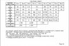
Heathkit W-5M Voltages.jpg

I suspect what is happening is that both 12AU7s are worn and not operating properly. You're dropping too much voltage across the 22K resistor because the second stage of V1 has 130 volts on its grid instead of 88, which is causing it to draw way too much current. I would strongly urge you, before changing any resistors, to check these voltages, which will tell us a good deal about the tubes themselves--and also to beg, borrow, buy or steal a fresh pair of 12AU7s to test in the amp. At the very least, try swapping out the pair from the other amp.

After the OPT ground lead fix, V1P6 increased to 240V vs 208 prior and 280V spec, so it's now 14% below, within Heathkit's 20% range. As for the age/quality of the tubes, that's worth looking into. While trying to figure out my distortion problem, I did swap the tubes, but frankly don't remember whether I measured before and after and if there was any difference, so I'll swap again and see what I see. As you correctly point out, I have no idea about the wear state of the tubes, though they came in boxes with hand-written measurements on them and the assurance of the seller that they had been checked. Of course that might mean nothing. But I can say, that the amp sounds very sweet and nice, so that argues against a bad tube, though it's clearly not 100% definitive.

The power transformers are underspec'd and will normally run hot, but checking the voltage from the output tube test points to ground will also tell us if they are drawing too much current and possibly putting a strain on the power transformer. You'd be best off to remove the cages during operation, as Pio1980 mentions.

OPT Tube voltages are all within 2% of spec, so I'm good there.

The Mullard 12AU7s are indeed very desirable but unless you have tested them, they may be worn out and not worth anything. ;-). 5881s are nice, but the Gold Lion KT66 will produce a more open and rich sound. They're the only good currently-manufactured KT66's IMO and are very nice. I use them in my Williamsons with excellent results.

As for the 5R4's, flaking getter (the silver stuff) is not good and these too should probably be replaced. If there is white powdery residue inside the tube, it is shot and should not be used.


What else? Do you think it'd be risky to even try the 5R4 with the flaking getter? It has now fallen to the bottom of the tube.

And if anyone reading this is in the Boston area and has a tube tester, I'd be eternally grateful if you'd be willing to help me test some tubes.

Thanks,

Kim

 
Those flakes are from the mica insulator. It's very common. I have a tube that looks like a snow globe without the water.
You think it's safe to use? I figure the flakes got dislodged when the tubes were shipped, even though they were super well packed.

Thanks for your help!

Kim
 
@zackthedog
P.S. If I change the resistors and the voltage problem isn't fixed, then I'd put them back and start to wonder about other causes. Does that strike you as reasonable, or are you opposed to even that? Thanks.
 
The single voltage standard for all other voltage measurements should be 6.3 VAC across the tube heaters, adjusted on variac. Any variations on input line voltage will change all voltage measurements, so there will be a practical range variation of measured voltages in real world use with normally occurring shifts in line voltage.
 
The reason I argue against changing the resistor values is that it creates a merry-go-round. Let's assume for the moment that V1 is worn out and not conducting properly. It's not drawing enough current, so it's not dropping enough voltage across the plate resistor. If you try to reduce the voltage supply to the plate resistor, it's going to draw even *less* current and therefore drop even less voltage across the plate resistor. You're chasing your tail, if you see what I mean. Changing resistor values will not cure the problem of a tube that isn't conducting properly.

The fact is that the first stage of V1 should be drawing about 6.5mA of current. If it's not, we need to find out why.

I would try swapping out 12AU7s and see if you get a better reading. Also, try this: with the amp off and V1 removed, measure the *resistance* from pin 3 to ground. It should read around 340 ohms.

The fact that the amp sounds great doesn't argue against a bad tube. Tubes are tolerant that way. ;-). But of course you want the amp operating optimally to produce the low-distortion sound it's capable of.
 
The reason I argue against changing the resistor values is that it creates a merry-go-round. Let's assume for the moment that V1 is worn out and not conducting properly. It's not drawing enough current, so it's not dropping enough voltage across the plate resistor. If you try to reduce the voltage supply to the plate resistor, it's going to draw even *less* current and therefore drop even less voltage across the plate resistor. You're chasing your tail, if you see what I mean. Changing resistor values will not cure the problem of a tube that isn't conducting properly.

This makes sense to me, but somewhat overlooks the fact that the PS is supplying too much voltage to begin with. But then I am not accounting for sag either. In any case, I will definitely try with the other set of tubes and see what changes. And of course, report back.
The fact is that the first stage of V1 should be drawing about 6.5mA of current. If it's not, we need to find out why.

I would try swapping out 12AU7s and see if you get a better reading. Also, try this: with the amp off and V1 removed, measure the *resistance* from pin 3 to ground. It should read around 340 ohms.
With V1 removed, the resistance from pin 3 to ground should be 470 ohms since there's a 470 ohm resistor on that pin which connects to ground. I'm not being a smartass, but I can see that from the schematic. And it's a brand-new resistor, so should be in spec, but I'll check anyway. ;-)
The fact that the amp sounds great doesn't argue against a bad tube. Tubes are tolerant that way. ;-). But of course you want the amp operating optimally to produce the low-distortion sound it's capable of.

I'm kind of hoping you are right about bad tubes. Because if that's the case, then I ain't heard nothin' yet, have I? Because this amp sounds pretty darn nice as it is.

Thanks again for your help.

Kim
 
This makes sense to me, but somewhat overlooks the fact that the PS is supplying too much voltage to begin with. But then I am not accounting for sag either. In any case, I will definitely try with the other set of tubes and see what changes. And of course, report back.
With V1 removed, the resistance from pin 3 to ground should be 470 ohms since there's a 470 ohm resistor on that pin which connects to ground. I'm not being a smartass, but I can see that from the schematic. And it's a brand-new resistor, so should be in spec, but I'll check anyway. ;-)

I'm kind of hoping you are right about bad tubes. Because if that's the case, then I ain't heard nothin' yet, have I? Because this amp sounds pretty darn nice as it is.

Thanks again for your help.

Kim

Wanna bet about that 470 ohms? ;-). That's what I always thought, but as Tim recently pointed out to me in another thread, with the feedback loop in place there's a parallel resistance to ground that reduces it. On my Williamsons, with a similar feedback loop, that 470 ohms becomes 330 ohms. If it weren't there no way you'd get 88 volts on the plate, it wouldn't be drawing enough current. In fact, you'd get about 130 volts on the plate, which makes me wonder if the feedback loop is properly connected.

Yes, you've got over-voltage because of the 117 primary on the power tranny, but at most that would get you 10-20 volts across the whole circuit.

If those old Mullards are shot, no, you haven't heard anything yet. ;-)
 
Wanna bet about that 470 ohms? ;-). That's what I always thought, but as Tim recently pointed out to me in another thread, with the feedback loop in place there's a parallel resistance to ground that reduces it. On my Williamsons, with a similar feedback loop, that 470 ohms becomes 330 ohms. If it weren't there no way you'd get 88 volts on the plate, it wouldn't be drawing enough current. In fact, you'd get about 130 volts on the plate, which makes me wonder if the feedback loop is properly connected.

Yes, you've got over-voltage because of the 117 primary on the power tranny, but at most that would get you 10-20 volts across the whole circuit.

If those old Mullards are shot, no, you haven't heard anything yet. ;-)

OK, you beat me to the punch, haha. I was re-reading the last half-dozen comments on the thread, and it suddenly occurred to me that I was wrong about the 470 ohms, because V1P3 also connects to the NFB circuit with has a 4.7K ohm resistor tied to the 16 ohm secondary on the OPT, which connects to ground. So my bad. It won't measure 470 ohms. But that said, all of the passive components were changed. (Except for the 30 ohm wirewound resistors, and the 330 ohm wirewound.) It also occurred to me that I have some fresh 12AU7s which came with the ST-70 input board I installed in my Dynaco in October. So I'll pop those in tomorrow and remeasure. Frankly, it'd be lovely if I'm simply looking at some bad 12AU7s, as it means the sound will be even better, and those tubes aren't all that spendy.

Thanks again. I'm eternally grateful for your help. If you're ever in Boston, I'd love to buy you a beer or something.

Cheers,

Kim

P.S. What Williamson amp are you using?
 
Last edited:
Back
Top Bottom