

You are using an out of date browser. It may not display this or other websites correctly.
You should upgrade or use an alternative browser.
You should upgrade or use an alternative browser.
Heathkit W4M Replacement Power Transformer?
- Thread starter tcdriver
- Start date
Register to hide this ad

Thank you for the lead. I found their website here: https://www.edcorusa.com/Edcor should have a suitable replacement,...

Dukiedook
Super Member
This one should fit the bill.
https://www.edcorusa.com/xpwr033
https://www.edcorusa.com/xpwr033
Looks like it will do nicely. Thank you for your help.This one should fit the bill.
https://www.edcorusa.com/xpwr033

Last edited:

I ordered it, but, since it is a build to order, it will take a while to get here. I do not expect that I will go to all the trouble to de-pot the original. I will know better, once it arrives, how well it will fit on the chassis.That looks like a nice replacement!
Please let us know if it can fit into the can ... even if you decide not to go that route.
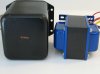
Update: I received the transformer and I have taken a few pictures to show the size difference between the original and the Edcor XPWR033-120. It appears that the Edcor would not fit in the original transformer cover unless the end bells are removed. Even then I can not say for sure if it would fit.


Last edited:

soundmotor
super modified
Measure the Edcor with the end bells off. It looks like it will fit in the Heathkit can. The one coming out won't have end bells on it either. However.....
Unpotting is a stinking, smoky process as is repotting. If you are going to do it, buy a second Edcor and do both PTs at the same time.
Unpotting is a stinking, smoky process as is repotting. If you are going to do it, buy a second Edcor and do both PTs at the same time.
I think that the Edcor may fit with the end bells off, however; I have already mounted and wired up the Edcor to the Heathkit chassis, so, at this point, I will not dismount it to remove the end bells to find out if it might fit. I really have no stomach for unpotting the Heathkit transformer.Measure the Edcor with the end bells off. It looks like it will fit in the Heathkit can. The one coming out won't have end bells on it either. However.....
Unpotting is a stinking, smoky process as is repotting. If you are going to do it, buy a second Edcor and do both PTs at the same time.
Notes: Notable differences between the two transformers are:
1. No center tap for the 6.3V winding on the Edcor
2. 5A for the Edcor 6.3V secondary vs 4A for the Heathkit
3. 200mA for the Edcor HV secondary vs 130mA for the Heathkit
4. Different footprint. The Edcor will not drop into the mounting holes in the Heathkit chassis.
Heathkit 54-29
Primary: 117V, 60Hz.
HV secondary: 760V CT @ 130mA
6.3V Secondary: 6.3V CT @ 4A
5V Secondary: 5V @ 3A
Edcor XPWR033-120
Primary: 120V, 60Hz.
HV secondary: 760V CT @ 200mA
6.3V secondary: 6.3V @ 5A
5V secondary: 5V @ 3A
The Edcor delivers more voltage than the Heathkit because it is lightly loaded. B+ is between 510 - 520V for a 120V input. This makes the original quad cap unuseable as it is only rated for 450V. I have modified the power supply, using stacked 400V electrolytic capacitors, so that it is somewhat similar to the W5.
I am currently looking into changing the bias to keep the 5881 tubes within their design power rating. One option would be to substitute some 6L6GC for the 5881. The 6L6GC has a much higher power rating.
The 6.3V supply is also running high at 6.7V, so I will see about making an adjustment to get it closer to the 6.3V standard. The 5V supply seems to be pretty close to the correct value.

Might be possible to get the B+ in check, by subbing in a 5U4 rectifier tube in place of the 5V4. It will drop a little more voltage, and since it pulls a little more from the 5V winding (still OK, since it's less than 4 amps), it might also pull down everything else (including the 6.3v heater winding) a little...
Regards,
Gordon.
Regards,
Gordon.
Thank you for the input. I will give that a try.Might be possible to get the B+ in check, by subbing in a 5U4 rectifier tube in place of the 5V4. It will drop a little more voltage, and since it pulls a little more from the 5V winding (still OK, since it's less than 4 amps), it might also pull down everything else (including the 6.3v heater winding) a little...
Regards,
Gordon.
soundmotor
super modified
You might try choke input rather than cap input. You should get a decent drop, slower B+ ramp up on the plates, & better regulation -

Thank you for the suggestion. I have already solved the capacitor problem by stacking caps, similar to how Heathkit did it for the W5.JJ electronic makes a 40/20/20/20 500V cap that drops in pretty readily if you can get the B+ down.
Putting a CL-80 thermistor on each leg of the power line might help bring the voltage down a bit.
Thank you for the suggestion. I had not thought of that.You might try choke input rather than cap input. You should get a decent drop, slower B+ ramp up on the plates, & better regulation -
Edit update: I tried the 5U4G in place of the 5V4. That resulted in a significant drop in the B+. With a 120Vac input the DC voltage at the rectifier output dropped from 499V with the 5V4 to 475V with the 5U4. I also increased the 360Ω cathode resistor to 438Ω. This knocked down the plate current a bit. Calculated plate current, per tube, is about 42mA. Tube power dissipation is about 18W.
I then measured the line input voltage at 123Vac. With the line input set to 123Vac, I measured the DC voltage at the rectifier (5U4) at 503V. Calculated output tube power dissipation is 20W, which puts me very close to the 23W Maximum Ratings (Design Center Values) for the 5881 tubes. The plate to cathode voltage is about 430V which is above the 5881 400V Maximum Ratings (Design Center Value).
Last edited:
Update: I measured the 6.3V heater voltage at 7Vac with a line input voltage of 123Vac. This was just too high for my liking. To reduce the heater voltage I added a 0.9Ω resistor in series with each leg of the heater secondary. This brought the heater voltage down to an optimum voltage. I took voltage readings with and without a Heath WA-P2 connected. The readings are in table 1 below.
Table 1. 6.3V heater voltage VS Line input voltage
VIN____No-preamp___w/ WA-P2
-----------------------------------------
117________6.19_________5.98
120________6.35_________6.14
123________6.52_________6.32
I still have some work to do, however; it is running as it is and I think that I will dig up some 6L6GC tubes to run in this W4. Thank you all for your help and suggestions. As you can see in the picture; this is a pretty rough looking example of a W4.
The previous owner(s) added a 4-pin socket to make a plug-in connection for a loudspeaker and also cut a hole near the power socket for some unknown reason. Underneath, the wiring is fairly sloppy, not one of the better examples of kit assembly.
Picture shows the Edcor XPWR033-120 mounted on the Heathkit chassis
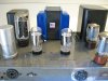
View from the back:

Table 1. 6.3V heater voltage VS Line input voltage
VIN____No-preamp___w/ WA-P2
-----------------------------------------
117________6.19_________5.98
120________6.35_________6.14
123________6.52_________6.32
I still have some work to do, however; it is running as it is and I think that I will dig up some 6L6GC tubes to run in this W4. Thank you all for your help and suggestions. As you can see in the picture; this is a pretty rough looking example of a W4.
The previous owner(s) added a 4-pin socket to make a plug-in connection for a loudspeaker and also cut a hole near the power socket for some unknown reason. Underneath, the wiring is fairly sloppy, not one of the better examples of kit assembly.
Picture shows the Edcor XPWR033-120 mounted on the Heathkit chassis
View from the back:
Last edited:
Update: Everything is together. I was able to find a couple of matched GE 6L6GC tubes in my tube stash, so I have no worries about the higher B+ voltage. B+ now measures 480V and the cathode voltage measures 44.4V across the 518Ω cathode bias resistor. This results in a quiescent bias current of about 43mA per tube and a power dissipation (quiescent) of about 18 Watts per tube.
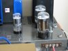
Heath W4-AM with GE 6L6GC output tubes:
It was not until I installed the amplifier in my system that I realized that the transformer was humming/buzzing a bit. Unfortunately, it was just audible, with no music playing, while seated in my listening chair, about six feet from the amplifier. This is the kind of thing that drives me nuts. So, I turned to the solution that I have used a few times in the past, with good results. I placed some rubber grommets between the chassis and the power transformer. This attenuated the humming/buzzing to the point that it was almost completely gone and not audible from my listening chair. The main noise contributor seems to be the rattle of the 5U4, but, still low enough in level that it is inaudible when no music is playing.

Now it is time to listen to some tunes.
Heath W4-AM with GE 6L6GC output tubes:
It was not until I installed the amplifier in my system that I realized that the transformer was humming/buzzing a bit. Unfortunately, it was just audible, with no music playing, while seated in my listening chair, about six feet from the amplifier. This is the kind of thing that drives me nuts. So, I turned to the solution that I have used a few times in the past, with good results. I placed some rubber grommets between the chassis and the power transformer. This attenuated the humming/buzzing to the point that it was almost completely gone and not audible from my listening chair. The main noise contributor seems to be the rattle of the 5U4, but, still low enough in level that it is inaudible when no music is playing.
Now it is time to listen to some tunes.
Last edited:
I do not understand the "balance buddy". Could you explain what that is? Thank you.I had one that was a little buzzy until I grounded the chassis to the balance buddy I used for a mutli-amp setup with active crossover.
Similar threads


- Replies
- 8
- Views
- 2K


