• The move to the new server is done. There are some software and database maintenance updates in process. This has us passing the hat around to help out. We appreciate any donations. Seriously, even a dollar helps. The payment page may be found here - https://www.audiokarma.org/support.html

RacerR

New Member
Hello - I've been lurking for a while, this is my first post.

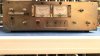
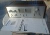
I recently bought a Pioneer SA-6700 - it's not in what I would call "collector" condition, but I'm hoping to perform whatever maintenance is required to make it reliable as a daily use amplifier.

The unit I purchased included the original operating instructions, and I found (online, PDF) and bought (a print copy of) the service manual.

I'm not new to audio electronics, but this is my first look at a '70's HiFi amp/system - so I will have a lot of stuff to figure out and learn.

This is also my first piece of Pioneer gear - so I don't know much about where the SA-6700 falls in the Pioneer model lineup / hierarchy.

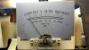
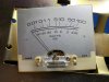
The SA-6700 I have is the model with two power output VU meters - I think there was an earlier SA-6700 with no meters.

Hello again.

-Rob
 

Attachments

  • Seller Photo Cropped.jpg
    Seller Photo Cropped.jpg
    73 KB · Views: 75
Register to hide this ad
Hello,
That's cool.
A lot of people on here refer to HiFiEngine (it's free) for owner's manuals and service manuals. You already have a print copy but sometimes it's good to have it electronically too, for zooming in etc.
I've also seen brochures there which would describe the various line-ups so you could learn more. Usually they are organized by year. I'll bet you could find a Pioneer brochure with the full integrated amp lineup that would tell you more.

Here's one interesting thread about the SA-6700:
https://audiokarma.org/forums/index.php?threads/pioneer-sa-6700-project.594128/

Anyway good luck!
 
I've had some time to take a look at the amplifier - here's my initial assessment.

The component references (C67, R124, etc... ) are from the Pioneer SA-6700 service manual schematic.

I'd be interested in reading thoughts on where I should begin with the maintenance/servicing.

Condition/Appearance Notes:
· Dusting of surface rust on back panel, speaker jacks, and in/out jacks
· Back panel is slightly bent – looks like someone was pressing the speaker releases too hard.
· Speaker cable release buttons are almost seized – difficult to operate
· Small amount of surface rust on metal top plate exterior, towards the back
· Unfinished metal surfaces have surface corrosion/build up throughout chassis
· Faux wood side panels have a small amount of pealing vinyl and a worn silver factory warning sticker on each side
· Top (real) wood plate appears OK:
o Some chewed edges where it mates with wood sides
o Stability and appearance of the wood top when assembled is OK​
· Silver faceplate has some dirt/discoloration
· Silver faceplate has some minor finish pitting on far right and left sides
· Knobs show wear, some nicks in the finish – not too bad
· Power switch sticky and difficult to operate
· Speaker selection knob sticky and difficult to operate
· Power Transformer has surface rust showing on black finish
· Years of dust cooked onto the top surface (component side) of the circuit board
· Noted some brown ooze on the top aluminum cap of C68 (Electrolytic, 220uF, 50v, 85 Deg)
· Noted some brown goo (probably glue) on:
o C67 (Electrolytic, 220uF, 50v, 85 Deg)
o C68 (Electrolytic, 220uF, 50v, 85 Deg)
o C75 (Electrolytic, 8000uF, 50v, 85 Deg)
o C76 (Electrolytic, 8000uF, 50v, 85 Deg)​
· Solder side of board has a lot of un-cleaned flux, probably from manufacturing
· Flux is discolored (more brown) near C67, C68, C75, C76, and Q15 (2SB507D)
· Noted what appears to be a cold solder joint on one of the legs of Q15
· Convenience outlets are very stiff and difficult to insert plugs into
· One of the switched convenience outlets has minor damage to the plastic exterior surface
o Does not appear structural, and should not affect functionality​

Pre-Maintenance Functionality Notes:
· Amp works – music plays, sounds fine
· Power LED lights when unit is on
· Power meters work
· Power meter lamps do not work
o PL1 (Incandescent, Axial, 8v, 55ma)
o PL1 (Incandescent, Axial, 8v, 55ma)​
· Peak indicator LEDs light on peak output
· The left channel peak indicator seems to light slightly earlier than the right channel
o Very small amount – channels “sound” like they are balanced
o This is with Balance control centered​
· Balance knob is very scratchy sounding in operation
· Input selection knob is a little scratchy sounding in operation
· Seems to run hot – smells like it’s running Really Hot
· The switched and unswitched convenience outlets function as expected
· Speaker connection releases are very stiff, almost seized

I'm gonna pull it apart and take a look at it with the meter as soon as I can.

Thanks!

-Rob
 
One of the first steps and sort of a standard procedure referenced on this forum is to clean the switches, selectors and pots and this is the most often-cited instruction on how to do it properly:
https://audiokarma.org/forums/index.php?threads/the-idiots-guide-to-using-deoxit-revisited.207005/

I think that would stand a good chance of helping or even solving these issues you raised and maybe more:

Speaker cable release buttons are almost seized – difficult to operate
Power switch sticky and difficult to operate
Speaker selection knob sticky and difficult to operate
Balance knob is very scratchy sounding in operation
Input selection knob is a little scratchy sounding in operation
Speaker connection releases are very stiff, almost seized

I hope that helps!
 
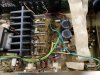
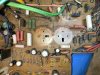
Here's an image of the board after a quick cleanup. It's far from spotless, but way better:
Board 001.JPG

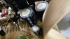
A suspect cap - C68 (220uF@50v):
Old Caps 001.JPG

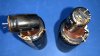
Caps C67, C68, C75, C76 out. Lots of crusty glue on the cap bodies, but C68 (small one on the left) looks like it's been dipped in goo:
Old Caps 002.JPG

Here's where the caps were stuck to the board - that glue is pretty tough - cleaning it will be difficult:
Crusty Board 001.JPG

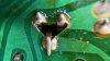
Here's the suspect solder joint on Q15:
Q15 Cold Solder.JPG
 
Last edited:
I'd remove the triac. I had one come to me that was fine except it had shorted.

Is the triac a common problem point in this circuit? It looks like that is part of the protection circuit - not sure I'd want to mess with that without an obvious failure... but if the mod makes sense and improves performance/reliability, I'd be open to performing it.
 
I've completed "Phase 1" of this project - which included the initial assessment and fixing some things that were obviously wrong:

=================================================================================
Steps taken for maintenance / repair (Phase 1):
· Removed:
o Wood side plates
o Top Plate
o Knobs
o Faceplate
o Bottom cover​
· Straightened the back panel – took only small effort to straighten, it looks good.
· Cleaned everything with DeOxit
o All pots thoroughly cleaned
o All switches thoroughly cleaned
o Speaker wire connectors cleaned
o Input/output jacks cleaned
o Convenience AC outlets cleaned
o Component side of board cleaned​
· Cleaned Faceplate and Knobs with warm soapy water
· Replaced questionable caps (a lot of glue on the board):
o C67 New Value: (Electrolytic, 220uF, 63v, 85 Deg)
o C68 New Value: (Electrolytic, 220uF, 63v, 85 Deg)
o C75 New Value: (Electrolytic, 10000uF, 63v, 105 Deg)
o C76 New Value: (Electrolytic, 10000uF, 63v, 105 Deg)​
· Fixed cold solder joint on Q15
· Reflowed a few (~5) other questionable solder joints
· Cleaned some of the dirtier (old flux) traces on the solder side with isopropyl & Q-Tips

Post-maintenance results/notes (Phase 1):
· Measured DC offset per AudioKarma forum procedures:
o Left channel: 11.7mV DC
o Right channel: 19.7mV DC​
· Amp works, music plays, sounds fine
· Power LED lights when unit is on
· Power meters work
· Power meter lamps still do not work
· Peak indicator LEDs light on peak output
· The left channel peak indicator seems to light slightly earlier than the right channel
o Very small amount – channels “sound” like they are balanced
o This is with Balance control centered​
· Balance knob operates smoothly and silently
· Input selection knob operates smoothly and silently
· Seems to run less hot, but still smells like warm old electronics when it runs though.
· The left channel peak indicator LED seems to light slightly earlier than the right channel
o Very small amount – channels “sound” like they are balanced
o This is with Balance control centered​
· Switched and unswitched convenience outlets function as expected
· Speaker connection releases operate smoothly – with only a little squeakiness
o I’ll probably lubricate these​
· Noted: Rail voltages (~37V both positive and negative) present on silver power transistor heat sinks
o I’m not sure if this is normal/expected – seems odd​
=================================================================================

I put the amp into use for an hour or two, playing music at volume levels right on the edge of power clipping, nothing has failed yet.

The amp sounds fine so far - I'm playing it through a set of old Klipsch Heresy speakers, which may be a little too large for testing this amp. I'm kind of surprised to see the power LEDs lighting with the volume only about 50% of the way up, but I'm not sure what is "normal" for this amp.

My next steps will be to figure out the meter lamps and identify any other potential problem spots or failing components. It would be nice to get DC offset balanced between right and left - the values I noted are in the acceptable range, but the left channel number (11.7mv) is better than the right channel number (19.7mv).

Let me know if you are aware of any obvious issues I could be missing that should be checked.
 
Oh - one other thing I've noted, and it appears to be a manufacturing error:

It took me a minute to figure out what was all over this transistor - I wiped most of it off before I figured I should get a photo, but it was originally completely covered:
IMG_1303.JPG

For comparison, here's the same transistor from the other channel:
IMG_1305.JPG

To me, it looks like the thermal compound was applied to the wrong side of first transistor shown. I'm wondering now, if the other (correct) side of the transistor is missing the thermal compound completely. I'd guess this has been like that since this unit was manufactured.
 
Is the triac a common problem point in this circuit? It looks like that is part of the protection circuit - not sure I'd want to mess with that without an obvious failure... but if the mod makes sense and improves performance/reliability, I'd be open to performing it.
Yeah the thing is it's the worst type of protection circuit to exist. It's common practice by many to remove it, this system exists in many Sansui's. Your call, but all it does it short the amp outputs to ground.
 
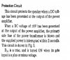
Here is a snip from the SM about the protection function (page 9):
protection.jpg
I see the triac as a potentially 'sacrificial' part, better for it to be damaged and protect your speakers. If you end up with an 8 vdc offset and a shorted triac you have probably already blown your output transistors. Make sure C77 and C78 are correct and good as the low pass filter function is critical to proper sensitivity. If they are low on capacitance the circuit will be too sensitive to large bass signals and may be false triggering.

It shorts the +40vdc rail to ground through two parallel 0.5Ω resistors.
 
Now, I’m moving onto the only “real” issue this amp had when I got it: The meter lamps don’t light.

The original Pioneer meter lamp parts, according to the schematic are two incandescent 8v 55ma axial lamps (labeled PL1 and PL2).

Looking around online, I don’t see a direct replacement for that lamp.

I figured there were three options:
1. Find an axial lead incandescent lamp that is as close to the original spec as possible.
· Pro: Will physically fit the meter and match the light output size/pattern.
· Con: May be tough to keep the circuit operating as intended with more or less draw from the lamps.​
2. Use a radial lead lamp that matches the electrical spec of the original lamps.
· Pro: I can match the voltage and wattage closely – 8v 50ma radial lead lamps are available.
· Con: May or may not fit physically and may or may not light the meter evenly.​
3. Buy or build LED replacements.
· Pro: Readily available, should work and be bright, multi colors to choose from.
· Con: I’m not sure exactly how the ready made axial unit function in the circuit: resistance?, power consumption?, etc.
· Con: I prefer incandescent light to LED on this old amp.​

I chose to start with option 1 – using physically matching axial lamps of a different voltage/wattage. The idea being to find an alternate part and get as close to original light output and current draw as possible.

I’m sure some of you are shaking your head already.
 
Last edited:
Here’s a quick overview (with some pics) of the meter lamp changing process I followed:

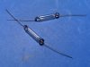
Get some new lamps:
New Lamps 001.JPG

Remove amp faceplate by removing all knobs and switch caps then removing the 4 nuts securing the faceplate.
Face Off 001.JPG
Face Off 002.JPG
Original Lamps 001.JPG

Remove the meters from the chassis far enough to remove the tape that holds the meter cover on the meter.
· The meters pull out – there was enough lead to get the meter out far enough to get the tape off.
· I cut the original meter cover tape – it maybe could have been pulled off.
· The reflective tape around the meter cover is delicate and tears easily

Desolder the original lamps:
Empty Meter 001.JPG

Solder in the new lamps:
New Lamps 003.JPG

Prep the meter cover with new tape
Meter Cover 001.JPG

Test first, or just replace the meter cover and fire it up
Working Lamps 002.JPG
 
The lamps I installed are 12v/100ma, compared with 8v/55ma in the original spec. I figured the 12v lamps wouldn't be too far off the original current draw when running at 7.5v in the Pioneer. They are a little further off than I thought they'd be though. I don't think I'm going to keep these lamps installed - the increased current draw is causing a couple of the big resistors to heat up quite a bit. Steps/Results noted below.

Steps taken for maintenance/repair (Phase 2):

· Replaced meter lamps
o PL1 New Value (Incandescent, Axial, 12v, 100ma)
o PL2 New Value (Incandescent, Axial, 12v, 100ma)​

Post-Maintenance results/notes (Phase 2):
· Amp works – music plays, sounds fine
o I played one full side of an LP: There was some heat on the board, but no other weirdness​
· Power LED lights when unit is on
o Power LED might be dimmer with new meter lamp lamps in the circuit​
· Power meters work
· Power meter lamps light
o Slightly dimmer than I expected
o New lamps draw more current.
o R100, R101, and R123 (2 Watt, 62 Ohm, Metal Oxide) are getting hot(!)​
· Peak indicator LEDs light on peak output
· The left channel peak indicator seems to light slightly earlier than the right channel
o Very small amount – channels “sound” like they are balanced
o This is with Balance control centered​
· Balance knob operates smoothly and silently
· Input selection knob operates smoothly and silently
· Seems to run less hot – still smells like warm old electronics when it runs though.
o Exception noted above (R100, R101, R123)
o The Q15 heatsink is only slightly warm to the touch​
· Switched and unswitched convenience outlets function as expected
· Speaker connection releases operate smoothly – with only a little squeakiness
o I’ll probably lubricate these​
· Noted: Rail voltages (both positive and negative) present on silver power transistor heat sinks
o I’m not sure if this is normal/expected – seems odd​
 
Here’s another thread detailing another user’s attempt at replacing the meter lamps on the euro version of the SA-6700 (the SA-606):

I’m thinking the lamps I’ve installed are too far out of spec to work in this amp long term, so I’m looking at the other alternatives – either LED or incandescent lamps electrically closer to the original spec
 
Here’s another thread detailing another user’s attempt at replacing the meter lamps on the euro version of the SA-6700 (the SA-606):

I’m thinking the lamps I’ve installed are too far out of spec to work in this amp long term, so I’m looking at the other alternatives – either LED or incandescent lamps electrically closer to the original spec

The lamps are fairly critical to correct circuit function, below is an excerpt from my reply to the previous thread link:

"D27 is a 2.7v zener, ZS-027. A 27v zener would be ZS-270. The circuit it is used in is a constant current source composed of D27, Q15 and R174, not a voltage regulator. It functions to stabilize the current to the lamps to maintain the same lamp brightness even when the source voltage varies. The source voltage is the main supply -40vdc side, which will vary greatly depending on the load drawn by the power amp, which will drop as low as -32.5vdc at full load (according to the schematic). It works by Q15 maintaining a constant voltage across R174 of 2vdc, the zener voltage (2.7vdc) minus the BE junction of Q15 (0.7vdc). 2vdc/15Ω = 133mA. The three 62Ω 3W resistors on the collector are ballasts that the current regulator uses to 'waste' excess power. They also protect the transistor from over-heating. Any variation in the load, like using different lamps, throws the circuit out of balance. The circuit was designed to match the lamps. If you want to use different lamps you could change D27 and/or R15 to change the constant current to match the 'new' lamp. Sorry if that is too much info, I got on a roll :rolleyes:."

This would be a great application for LEDs as you could adjust the current for the LEDs by modifying the circuit values of the constant current regulator.
 
The lamps are fairly critical to correct circuit function, below is an excerpt from my reply to the previous thread link:

"D27 is a 2.7v zener, ZS-027. A 27v zener would be ZS-270. The circuit it is used in is a constant current source composed of D27, Q15 and R174....

Right on, thanks - I'm on the same page now. I was thinking about messing with R124 (15 Ohm) - it's inline between Q15 and the lamps, but I'm not sure yet how that will affect the way D27 behaves. I could add another resistor further down the line in series to get the current where it needs to be, but with the 12v/100mA lamps - they'd be super dim.

I'm considering two things now, either LEDs or shelving the project until I can find 8v/55mA lamps for it.

I'm looking at LEDs at the moment, and not entirely happy with the color and quality of light compared to an incandescent lamp in this amplifier:

I'm also going to widen the net and try to find some 8v/55mA axial lamps - that'd be the ideal solution in my mind.

Thanks again!

Edit: Fixed the R124 reference above - I had originally written "R15" - sry!

-Rob
 
Last edited:
Right on, thanks - I'm on the same page now. I was thinking about messing with R15 - it's inline between Q15 and the lamps, but I'm not sure yet how that will affect the way D27 behaves. I could add another resistor further down the line in series to get the current where it needs to be, but with the 12v/100mA lamps - they'd be super dim.

I'm considering two things now, either LEDs or shelving the project until I can find 8v/55mA lamps for it.

I'm looking at LEDs at the moment, and not entirely happy with the color and quality of light compared to an incandescent lamp in this amplifier:

I'm also going to widen the net and try to find some 8v/55mA axial lamps - that'd be the ideal solution in my mind.

Thanks again!

-Rob

An exercise in Ohm's law, and just for fun bulb substitution calculation:
Two 100mA lamps in parallel would need 200mA through the Q15 CCS, so R15 would become 10Ω dissipating 0.4W, I would use a 1W resistor. The original 113mA through 62Ω resistors would drop 7vdc each, times 3 resistors, means 21vdc dropped across all 3, for about 80mW each. The original lamps used a nominal 7.5vdc, which would need to increase 4.5vdc to get 12vdc. The three resistors need to drop 4.5vdc less to compensate, for a total new drop of 16.5vdc. 16.5vdc/200mA = 82.5Ω total at 3.3W or 1.3W per resistor. 82.5/3=27.5Ω The closest 5% standard value resistor is 27Ω. A 27Ω 2W(or 3W) resistor would work fine. 40 - (12 + 16.5) = 11.5vdc across the transistor, at 200mA makes 2.3W transistor dissipation. The original transistor, 2SB507 is a 60V 30W TO-220, which should still work fine. Being an obsessive perfectionist I would add a bigger heatsink.

Did I make any errors here?
If I calculated correctly you could change 3 resistors and use the 12v bulbs (if you like the color and brightness).
Sorry if I went overboard . . . :rolleyes:
 
Last edited:
Back
Top Bottom