• The move to the new server is done. There are some software and database maintenance updates in process. This has us passing the hat around to help out. We appreciate any donations. Seriously, even a dollar helps. The payment page may be found here - https://www.audiokarma.org/support.html
I think your math is solid, but I'd still worry about unintended consequences/butterfly effect on the rest of the circuit. For instance - how would the added voltage on the lamps affect Q3? It looks like the base of Q3 is controlling the power to the peak indicator LEDs, and the base of that transistor is connected directly to the negative side of the lamps.

I think the best bet would be to find the factory spec lamp, or figure out how to match the characteristics with an LED in circuit.

I think this info is correct, but take it with a grain of salt - the original lamp specs are:
Lamp: 8v/55ma Axial Incandescent
Voltage: 8 volts
Current: .055 amps
On Resistance: 145.46 ohms
Watts: 0.44​

I don't think the lamps are behaving exactly like that in the circuit though, since they are only getting 7.5 volts. Figuring out exactly how the lamp is behaving in the circuit is tough (for me) because the ratio of circuit voltage to on-resistance is on a curve with incandescent lamps. Lol - I've actually demonstrated how bad I am at figuring that out - I put 12v/100ma lamps in the circuit.

I have the axial LEDs in hand already, but I'd really prefer sticking with incandescent lamps.

Still not sure exactly how I'm going to move forward here yet.

Thanks for the input - any info or guidance that can be provided is appreciated!

-Rob
 
While the original lamps were incandescent, and a purist would tend to replace those with in-kind parts, there may be other considerations which could affect your decision.

The manufacturer most likely designed the unit to last 10 years, not 40+. The heat generation of the incandescents slowly stresses the plastics used in lamp diffusers, circuit boards, meter housings, bezels, and the surrounding hardware. This cumulative damage is almost impossible to reverse or repair. About the best we can do is to prevent additional damage, and that means reducing the temperature. The options are limited to either a remote light source and fiber optic cables, or lower temperature lamps, a.k.a., LEDs. In the recent past, LEDs with an almost identical color temperature (wavelength) of the incandescents have become available. Moreover, lamp assemblies and COBs are available with inherent rectification and current regulation, making them suitable for operation on AC supply circuits. Thoseshould be evaluated/considered.
 
I think your math is solid, but I'd still worry about unintended consequences/butterfly effect on the rest of the circuit. For instance - how would the added voltage on the lamps affect Q3? It looks like the base of Q3 is controlling the power to the peak indicator LEDs, and the base of that transistor is connected directly to the negative side of the lamps.

I think the best bet would be to find the factory spec lamp, or figure out how to match the characteristics with an LED in circuit.

I think this info is correct, but take it with a grain of salt - the original lamp specs are:
Lamp: 8v/55ma Axial Incandescent
Voltage: 8 volts
Current: .055 amps
On Resistance: 145.46 ohms
Watts: 0.44​

I don't think the lamps are behaving exactly like that in the circuit though, since they are only getting 7.5 volts. Figuring out exactly how the lamp is behaving in the circuit is tough (for me) because the ratio of circuit voltage to on-resistance is on a curve with incandescent lamps. Lol - I've actually demonstrated how bad I am at figuring that out - I put 12v/100ma lamps in the circuit.

I have the axial LEDs in hand already, but I'd really prefer sticking with incandescent lamps.

Still not sure exactly how I'm going to move forward here yet.

Thanks for the input - any info or guidance that can be provided is appreciated!

-Rob
A little bit lower voltage on an incandescent lamp (0.5v) will let it run a bit cooler and look a bit warmer.

Looking at the operation of Q3 (on the AWX-136 board) it is used as a resistive switch and is conducting with a collector current of 20mA. It is powered by the -40vdc supply through R17, 1kΩ 2W, with 20v across it, and the emitter feeds the cathode resistor of the power indicator LED. According to the schematic's posted voltages the BE junction of Q3 is 0.8vdc. If this is accurate Q3 is hard on and a few more volts on the base won't make any difference, except the LED may be marginally brighter. Even if Q13 is completely saturated the max current the power LED will see is about 29mA, up from 20mA, which probably won't hurt it at all (imho, can not locate a datasheet). The anode of the LED is connected to ground. I see no connection related to Q3 (except -40vdc power and ground) in common with the Peak LEDs circuit that will affect the operation of the peak indicator LEDs. The -40vdc supply for the Power indicator and Peak LEDs comes onto the AWX-136 assy at pin 9, and comes directly from the junction of D21 and D22 at the power supply full wave rectifier. It does wander around on the schematic drawing making it hard to follow, though.
Please (anybody) correct me if my analysis is faulty . . .
 
Last edited:
A little bit lower voltage on an incandescent lamp (0.5v) will let it run a bit cooler and look a bit warmer...

Quick question - I don't think I'm going to do this, but...

The circuit design calls for two 8 volt / 55mA lamps in parallel.

How far off of that would two 8v/100mA lamps be if connected in series?

Some Notes:
- Lamp brightness may be an issue
- It seems like it would be pretty easy to change how the meter lamps are connected.
- Putting two lamps in series would also make it twice as likely that the circuit will fail - like an old string of Christmas lights.​

-Rob
 
Quick question - I don't think I'm going to do this, but...

The circuit design calls for two 8 volt / 55mA lamps in parallel.

How far off of that would two 8v/100mA lamps be if connected in series?

Some Notes:
- Lamp brightness may be an issue
- It seems like it would be pretty easy to change how the meter lamps are connected.
- Putting two lamps in series would also make it twice as likely that the circuit will fail - like an old string of Christmas lights.​

-Rob
That effectively becomes a 16v @ 100mA circuit. Same calculations would be needed to figure component changes, total power dissipation increases because current has almost doubled. Since the lamp circuit runs off of the -40vdc rail there is plenty of headroom.

Lamp brightness would be the same as long as the total voltage across and current through each bulbs remains correct for that bulb. Lamp brightness in an incandescent filament bulb is related to power dissipation, so an 8v @ 100mA bulb will probably be brighter. A bulb specified for 100mA will be dim @ 55mA.

Two lamps in series does not change the failure 'rate' but a failure in one bulb darkens both, just as you note with old series strung Christmas lights.
 
Last edited:
the lamp brightness is know where near linear, so 1/2V rated V is not 1/2 brightness
colour temp when run at 1/2 the rated supply V is not the same either, so I do not recommend to do this, get the correct lamps or use LEDs
 
Thanks again for the responses/input, yeah - getting the correct lamps is the way to go. I think I found some, so I should have an update here soon.

-Rob
 
I found some 8v/55mA lamps:
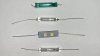
- Top: Original 8v/55mA blue/green lamp
- 2nd from Top: 12v/100mA lamp
- 2nd from Bottom: 8v warm white LED
- Bottom: New 8v/55mA clear lamp​
Four Lamps 001.JPG

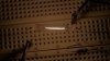
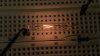
The 8v/55mA lamp contains a much shorter/thinner filament than the 12v/100mA lamp.

Here is a shot showing the filament of the 12v/100mA lamp:
Filament 12v 001.JPG

and here is the 8v/55ma filament:
Filament 8v 001.JPG

These should get the circuit working as designed - even if the light is brighter/warmer without the blue lamp coating.

-Rob
 
I have my SA-6700 hooked to my computer speakers (JBL530) and it is running now (Porcupine Tree),

I replaced my lamps about ten years ago. I used green theater gel over the replacement incandescent lamps. The thing is that one lamp has already expired.
Next time I'm using LED.
I wasn't planning on using the existing lamp power supply, I was going to run the LEDs off some other source with its own power supply on a little board.

Though I see you have an 8V LED where did you get that? It looks like the best idea.

Screen Shot 2020-02-04 at 8.26.46 PM.png
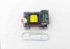
Mini-AC-DC-Isolated-Power-Module-5Vout-700mA-3.5W-01-640x460.jpg
SA-6700 insides.JPG
 
Last edited:
Though I see you have an 8V LED where did you get that? It looks like the best idea.
- These actually seem like the easiest ones to find now - search your favorite auction site for "8v Axial LED". Many of the listings that show up will have a photo of a HiFi component as the main image.
- The gel around your lamps looks nice - I've done something similar to LEDs with gel and clear heatshrink tubing. It's possible I'll wrap the lamps in this one before I'm finished with it.​

Wow though - your amp is so much cleaner than mine, it looks great. Mine looks like it may have been left out in the rain, more than once. I may eventually have to find a cleaner one.

Also, you have VR3 and VR4 to adjust the meter levels. That's cool. Mine only has fixed resistors there, one of which is visible in the 1st photo of my board in this thread.

My next steps will be to get the new lamps installed and clean the old silver stickers off the side panels.

I'll post an update when I make some progress.

-Rob
 
Here is the amp powered on and running with the new 8v/55mA lamps:
Running 8v-55ma Lamps 001.JPG

Looks good to me - I don't think I'm going to wrap the lamps with anything. The 8v lamps are much brighter than the first set of 12v lamps I tried.

I played one side of an LP with the volume at about "4", and there is no unusual heat coming from the board. The heatsink on Q15 is the warmest component in the lamp circuit now - the 62Ohm/2 Watt resistors are running much cooler with the 8v lamps.

I need to get the stickers off the side panels and do a few other small tweaks, and I think it'll be ready for daily use.

I'll post an update when I make some progress.

-Rob
 
The 'white' lights do seem more fitting with the silver motif.
That's what I think too. To me, the lamps I have in there now look really close to the Pioneer literature from the time.

Isn't this what they looked like when they were new?:
Catalog Image 001.jpg

That's the look I was going for.

-Rob
 
I think this thing is done.

Summary of maint. performed:
  • Disassemble
  • Replaced C75 & C76
    • Original: Elna 8000uF 50v 85 deg Electrolytic
    • Replacement: Rubycon 10000uF 63v 105 deg Electrolytic
  • Replaced C67 & C68
    • Original: Elna 220uF 50v 85 deg Electrolytic
    • Replacement: Nichicon 220uF 63v 85 deg Electrolytic
  • Replaced Meter Lamps (PL1 & PL2)
    • Original: 8v 55mA Axial Incandescent - Blue/Green tint
    • Replacement: 8v 55mA Axial Incandescent - Clear
  • Reflow suspected cold solder joints
    • Q15 specifically (completely desoldered/resoldered)
    • plus a few others that looked like they needed it.
  • Thorough cleaning of all pots with Deoxit
  • Thorough cleaning and lubricating of all mechanical components (speaker connections, convenience outlets, etc..)
  • Remove silver side panel stickers using isopropyl/credit card.
  • Clean faceplate and knobs with warm soapy water
  • Reassemble
The amp works really well now - using it, it feels like a new amp. No unusual heat anywhere on the board after extended high volume play. All the knobs turn easily and smoothly; no pops, crackle, or fuzz anywhere. The volume comes on quickly - peak indicator LEDs start hitting with the volume at around 5 or 6 with rock/metal CDs coming from an analog CD player on the aux input.

As a whole, I'd say the amp was really easy to service - all the parts are physically accessible and most of them can be found and or replaced with equivalents easily enough. No issues getting my DMM probes anywhere I needed to put them. The lamp circuit was really interesting though - I'll never take an IC voltage or current regulator for granted again.

Going with incandescent meter lamps - I may have to replace them sooner than an LED set. But the amp seems to really like the correct incandescent lamps - all the unusual board temps and channel balance issues (seemed to) clear up once I put the original spec lamps in. And the truth is - I could qualify for an F1 pit crew with these meter lamp changes now - I think the last lamp swap I did took 15 minutes from playing music to bench and back to playing music.

I dig the aesthetics of the late '70s Pioneer stuff for sure: Silver metal face, (faux) wood sides, analog VUs. More or less exactly what I was looking for.

It's living on a shelf now - I'll get some better photos of it once I get a cabinet for this stuff.
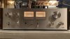
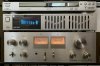
Stacked 001.JPG

I'm not sure how well it matches the rest of the kit, but at least it's all silver. I'm sure I'll be changing stuff frequently until I get it to where I want it. I'd say this is just the first round really, since I'm essentially rebuilding my system from the ground up. Getting the turntable sorted out will be the next step.

In the CD player for this photo:
Remain in Light 001.jpg

-Rob
 
Last edited:
Back
Top Bottom