• The move to the new server is done. There are some software and database maintenance updates in process. This has us passing the hat around to help out. We appreciate any donations. Seriously, even a dollar helps. The payment page may be found here - https://www.audiokarma.org/support.html

help identify 3 tube phono amp...

knockbill

Lunatic Member
hi guys...
i just joined today,,, hope this post is on the right forum....
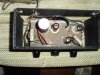
i have an old 3 tube amplifier from a 1960s phono... i am pretty sure its a zenith, possibly a 3L03 chassis...can anyone help identify it?

i'd like to find a schematic for it, i am planning on replacing the caps, it has two 50c5 and one 12ax7...

thanks in advance for any help you can offer,
john
 

Attachments

  • PC030120.JPG
    PC030120.JPG
    81.5 KB · Views: 221
  • PC030119.JPG
    PC030119.JPG
    82.3 KB · Views: 182
Register to hide this ad
Take care! It is a "hot chassis" design, i.e, no power transformer so if you plug the blades the wrong way, the chassis will be energized... If you're lucky (like me), you will feel a good jolt but it could also (in the worst case) kill you.
 
Take care! It is a "hot chassis" design, i.e, no power transformer so if you plug the blades the wrong way, the chassis will be energized... If you're lucky (like me), you will feel a good jolt but it could also (in the worst case) kill you.

got it,,, thats why i put a polarized plug on it....

any info on teh chassis identity or schematic?
 
Here's the schem for the 3L03 chassis (LPS50 portable phonograph).

Certainly fits your description with correct tubes, two dual-ganged pots for vol and tone and a single balance. Solid state rectifier.

Last one of these types that I recapped I added an extra filtering stage and took the OT taps off that second stage rather than the first - it hummed too much. This made a bit of improvement but still pretty hummy with bigger-than-4" speakers.
 

Attachments

Here's the schem for the 3L03 chassis (LPS50 portable phonograph).

Certainly fits your description with correct tubes, two dual-ganged pots for vol and tone and a single balance. Solid state rectifier.

Last one of these types that I recapped I added an extra filtering stage and took the OT taps off that second stage rather than the first - it hummed too much. This made a bit of improvement but still pretty hummy with bigger-than-4" speakers.

thank you for teh schematic,,, i will print it and try to make the mods you suggested,,, can you pencil them in teh schematic? i ordered the new caps earlier this week, should get here saturday,,,
i've built and worked on radios/audio equipment over the years, i can follow a schematic,,but i dont know enough to make modifications,,, i'd like to learn, tho....

regards,
john
 
Last edited:
Sure; I can cut 'n paste with the best of them.

Take a look at what I added to the circuit: one cap and one resistor between the diode and what was the first cap.

I labelled the new cap C3C but it would not be part of a can cap, it would be a separate. And the value is not hyper-critical. I would use something from 100uF to 220uF.

The new resistor is labelled as 100Ω but I typically use 47Ω, and I have a supply of 10W so I use them. I like the lower value because it drops less voltage in an already limited B+ supply.

The idea of adding an additional stage is simply to lower the AC ripple a bit before it hits the branch circuits such as the OTs and then the power tube screens, etc, on down the line. This is already a challenge with Single-ended amplifiers (no hum-bucking in the OT) but with the series string rigs like this you need any edge you can find.

Have fun!
 

Attachments

  • 3L03 cut.jpg
    3L03 cut.jpg
    41.3 KB · Views: 40
thanks again for taking the time .... i think this little amp is just teh size project i need to get some "hands on" experience with amps...

is there any advantage to putting a full bridge in teh power supply, to replace the diode? will i be able to filter it more?
 
got it,,, thats why i put a polarized plug on it....

Won't save your life. Just FYI. A hot chassis is still dangerous.

I'm sorry I can't help you with schematics and I don't want to play nervous nanny, but I did want to throw that in. Do as you see fit, of course. I'd just hate to see any AKer electrocuted. OK, maybe one or two. Just kidding.
 
thanks again for taking the time .... i think this little amp is just teh size project i need to get some "hands on" experience with amps...

is there any advantage to putting a full bridge in teh power supply, to replace the diode? will i be able to filter it more?

You're welcome. Practice is good, and it'll give you a good frame of reference for when you move up to one with a PT.

Can't do a full bridge on this one, sorry. The challenges here are not only the ripple current, but also the filaments. Since they are not twisted parallel pairs they will introduce some hum. Then you've got lead dress and grounding scheme pitching in their evil ways too. The reality is that these sets - just like the AA5 radios they were inspired by - were typically designed to power a speaker that can't even reproduce 60Hz, so not much care was taken to minimize hum. It comes with the package.

Speaking of radios, though, the safety and updating techniques (X/Y rated caps, switching the hot line rather than the neutral, etc) discussed on radio restoration sites apply to your Zenith, too. They can be a great resource for you.

Lol@Wigwam with the 'maybe one or two'
 
A polarized plug is not safe.I have found outlets that are wired backward. The only real way to safety that amp is to isolate the chassis from the power outlet. Simplest way is to use an isolation transformer. PLEASE!

Shelly_D.
 
You're welcome. Practice is good, and it'll give you a good frame of reference for when you move up to one with a PT.

Can't do a full bridge on this one, sorry. The challenges here are not only the ripple current, but also the filaments. Since they are not twisted parallel pairs they will introduce some hum. Then you've got lead dress and grounding scheme pitching in their evil ways too. The reality is that these sets - just like the AA5 radios they were inspired by - were typically designed to power a speaker that can't even reproduce 60Hz, so not much care was taken to minimize hum. It comes with the package.

Speaking of radios, though, the safety and updating techniques (X/Y rated caps, switching the hot line rather than the neutral, etc) discussed on radio restoration sites apply to your Zenith, too. They can be a great resource for you.

Lol@Wigwam with the 'maybe one or two'

thanks again for the info..... i made a couple copies of teh schematics,,, so i'll draw in teh changes you showed me...
i should have asked for teh schematic before i ordered teh caps... now i'm gonna need the other 150mf you added!!!

yep, the radios are wired the same way,, i have two 1940s philco's that i re-capped a while ago,,, same hot chassis.... the only safe thing about them is teh wood cases,,, teh x y safety caps are a good idea also... i have a polarized plug on the little amp,, and stdp switch would also be a good addition...

don't lose any more sleep over teh hot chassis,,, i've been a licensed electrician for over 40 years,,, i don't have any reverse neutrals in my house, garage or sheds for that matter... i have an isolation transformer, and a gfi at teh work bench,,,, so, i'm not working on it in teh bath tub....
hell,, its not even the hottest circuit i've worked on this week!!!!!!!!!!!

thanks again for taking the time to send me the schematics...
regards,
john
 
got it...

the caps came this morning, so i replaced the two electrolytics,,, still no go,,, i found the "5 watt special fuse" was open,, and replaced it with a wire wound resistor i had,,, and got it going...

is it ok to use teh resistor, and put a line fuse in,, or can i replace teh "special fuse" zenith used originally,, or any other suggestions...

thanks again for the help, i realize its a dangerous, noisy, underpowered little amplifier,,, but its good for learnin' something about tube amps, and thats teh exercise here,,,
regards,
john
 
is it ok to use teh resistor, and put a line fuse in

Yes, do this. Shouldn't need more than a 2A fuse but you can put an ammeter in series there and see what it's drawing.

Have you done the signal caps yet?

RWood
 
ok,, i'll get a fuse holder,, or, just solder it in...

signal caps? are they the two .047's,, or the two small ones (.0047)off the tone control? i put one of the .047, the one to the chassis, with test leads,,,but, i'm thinking they need to be soldered in, so the wires are shorter...

lots off issues here,, i guess its mostly in the original design,,, the more i work on it the more questions i have...

i found a write up about getting rid of hum in this type of amp,,, now that its working, i'm going to see how quiet i can get it...

as always, thanks for your reply,
john
 
These little guys get into your head don't they? I have a 3-tube widow-maker, a Kay, that gave me bad dreams for a while.

Yes, the .0047s are the tone caps. the main coupling caps are the .01s that block DC but pass the AC signal on to the power tube grids.

This amp has a very strange way of biasing the preamp tube. There is B+ voltage going through a pair of 47Ks to the cathodes of the 12AX7. This counters the other B+ going through the 270K anode resistors to the plates. I've got a couple of Bogens that do this too - its unusual. You will typically see a simple cathode resistor to ground, sometimes bypassed by a cap. And in earlier circuits you'll see the cathode grounded and a really high grid-to-ground resistor (called grid leak bias or contact bias).

Btw, if you are looking to jack up the gain a bit try a cathode bypass cap on each power tube. Go parallel across the cathode resistor with something like 33uF to 50uF (even 100uF if you have it), 25V or 50V. Make sure the + end of the cap is on the cathode. I bet you'll like it!
 
thanks again for replying,,,

i drew the "newest mod" you gave me on my schematic,,,, i was just rooting thru a junk drawer for a rubber band, and i pulled out a 25v, 47uf cap... theres a coincidence for ya..,,, by teh time i get this thing figured out,, i may be able to build my own little amp!!!!!

i am going to wire teh new filter caps in teh chassis,,,
i've been reading ( found a site called basic vac tube amp design),,,about twisted pair, 18 gauge leads,, dressed into teh opposite side of teh chassis from teh input, for the filaments,,, seems like it could be done pretty easily,,, its one of teh first priorities for eliminating noise,,,i already moved teh input ac line and switch as far away as i could, so this may be my next step... i need to find some 5w resistors soon... i dont have them around...

well,, i think you're giving me a crash course in amp design,,, and i really appreciate it...

regards,
john
 
K bypass caps...

"Btw, if you are looking to jack up the gain a bit try a cathode bypass cap on each power tube. Go parallel across the cathode resistor with something like 33uF to 50uF (even 100uF if you have it), 25V or 50V. Make sure the + end of the cap is on the cathode. I bet you'll like it! "

i finally found a pair of 100@25V caps to try,,,, seems to have made a difference in volume available, and bass...
i noticed that this modification dropped teh K voltage about 13-14V,,, is that what i should expect? any reason not to leave teh 100mf caps, or would teh lower values work better?

thanks,
john
 
Last edited:
i noticed that this modification dropped teh K voltage about 13-14V,,, is that what i should expect?

Double check that reading on the 0-20VDC scale. Cathode voltage (pin 1 to ground) should be around 7V total in that circuit, so it would not have dropped as much as you reported.

Also confirm that the + end of each of your two bypass caps is on pin 1 and the - end of each is at ground.

Only reason to reduce the value from 100uF is if it sounds too bassy, in which case you would try 47uF, 33, 22, 10 etc until you are happy. The bypass cap should not affect the DC cathode voltage much at all.

here are the specs for your power tubes:

50C5.gif
 
Last edited:
"Double check that reading on the 0-20VDC scale. Cathode voltage (pin 1 to ground) should be around 7V total in that circuit, so it would not have dropped as much as you reported."

good to hear from you again... i misspoke,,,sorry,, i meant plate voltage,,,its suppose to be 117V,, and now, after i replaced teh caps,, and 1W & 5W resistors, its 116.4 & 116.2,,, within specs, i guess...teh K voltage to chassis ground is about 8V calls for 7.1,,, i tried the 100mf caps,, and settled on 47mf...

i tried to put in the extra filter (100 ohm 5W, and100mf 150V cap,,, but i must have not read teh schematic addition right, because it didn't work...i have to go thru it again and check values,,, i could smell it getting hot, so i shut it down,,,now i have a little distortion at full volume... i thought i had gotten rid of most of it with the new resistors...

i'll try again,,, thats is teh reason i am using this little amp to learn on,,,

thanks for your help,,,
the K bypass caps made a noticeable difference,
regards,
john
 
"i tried to put in the extra filter (100 ohm 5W, and100mf 150V cap,,, but i must have not read teh schematic addition right, because it didn't work...i have to go thru it again and check values,,, i could smell it getting hot, so i shut it down,,,now i have a little distortion at full volume... i thought i had gotten rid of most of it with the new resistors..."

i've been studying the schematic addition,,, it seems the new cap, c10c (150@150v), is parallel with the diode, then the 100ohm 5w resistor lowers the dc to the c10b, cap...i'm just double checking the addition,, should the case, (neg) side of the added cap be on the hot side of the .047,,, or the neutral side, like the other two.... (10a,c10b) ?
just trying to find out what went wrong.... without burning up components!!!

thanks for any insite,,
john
 
Last edited:
Back
Top Bottom