• The move to the new server is done. There are some software and database maintenance updates in process. This has us passing the hat around to help out. We appreciate any donations. Seriously, even a dollar helps. The payment page may be found here - https://www.audiokarma.org/support.html

help identify 3 tube phono amp...

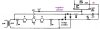
Yeah, on second look I did make a mistake on that schem re the .047 cap. I should have placed it to the right of the spot where the new cap is grounded. Sorry if I made you blow up a capacitor.

The new cap should be grounded in the same place you have the existing cap grounded. The high voltage goes to the + end of the new cap, and then the 100Ω carries the B+ to the next cap (previously the first cap).

The concept here is that you are adding an additional stage of filtering, with just a little resistance between it and the next stage. The branches off of the filtering caps do not begin until the B+ gets to what is now the second stage. This is done simply to help reduce the ripple current.

RWood
 
Yeah, on second look I did make a mistake on that schem re the .047 cap. I should have placed it to the right of the spot where the new cap is grounded. Sorry if I made you blow up a capacitor.

The new cap should be grounded in the same place you have the existing cap grounded. The high voltage goes to the + end of the new cap, and then the 100Ω carries the B+ to the next cap (previously the first cap).

The concept here is that you are adding an additional stage of filtering, with just a little resistance between it and the next stage. The branches off of the filtering caps do not begin until the B+ gets to what is now the second stage. This is done simply to help reduce the ripple current.

RWood
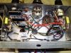

Don't be sorry,,,I'm obviously learning something!!!!!!!! Its my fault,, i noticed the difference in teh schematic, and tried it anyway...
Thanks for your help, again,,,I don't have any way of testing caps, except for shorting,,, do you think teh new one, is the only one thats gone? all teh new resistors seemed to survive,,,

keep in touch,,, i have lots more questions,,,,

regards,
john
 
Got the 3rd stage working....

I wired in teh the 3rd filter stage,, sounds pretty good, with teh modifications,,,I'll try it on better speakers, but so far, so good,,,
Regards,
John
 

Attachments

  • PC140016.JPG
    PC140016.JPG
    82.7 KB · Views: 55
  • PC140018.JPG
    PC140018.JPG
    79.3 KB · Views: 21
Nice work there and glad to hear it sounds good - that is the ultimate test.

I like the way you twisted the pair of filaments even though they are in series. I have only done that for parallel pairs but will try this on my next series string. Can't hurt and it looks like it could help. thanks.
 
Thanks for all your help.... it's a fun little project.. i read about twisting teh filament lines, on a series ckt as a way of reducing the noise,,, also, dressing them in teh corners of teh chassis, as far away from everything else as possible,,,

i was thinking about putting in a switch, to add 2 more K caps, (i have 47 in now) kinda like a bass boost... teh range was something like 10-33mf for less bass,, and up to 100mf or so for more,,, so if i was add another 47-68mf with a switch, i could get "bass on demand", and still refine it with teh tone control... definitely need to use better speakers, tho...

sound feasible??

regards,
john
 
That's very possible and you could do it on a SPDT switch. Ground the center lug where the Rk's are grounded, then the L&R Ck pair (A) negative ends go to one leg of the switch; L&R Ck pair (b) negative ends go to the other leg.

Another way you can play with bass response is to increase the value of the .01uF coupling caps. You could try .022. .047, .068 and .1. Since caps in parallel are additive, you could temporarily jumper them in on top of the .01s you have in there now. I'd use alligator clips, and watch out for the 100vdc or so. One hand in pocket if you do this live (but you know that).

The downside to doing this, though, is that you are going to amplify whatever hum that amp is now generating. So I would evaluate these changes with the amp playing through the speakers that you will likely use with it.

Sounds like you are having fun. :yes:
 
thats how i planned to do it,,, i first thought of adding a DPDT switch to select between two different sets of caps,, but it would be easier to just parallel a set to add more capacitance to teh K circuit...its gettin a little tight in the chassis!!!

i will try jumping the .01's, just to see teh difference, but, its easier to access teh K's....

i don't work on anything live,,, unless i have to...

any other "improvements" i can try,,, like a pre amp circuit to use a mag phono cartridge?
 
"Another way you can play with bass response is to increase the value of the .01uF coupling caps. You could try .022. .047, .068 and .1."

I finally got a chance to try to add a bass boost,,, First, i doubled teh K cap, but that didn't help,, so I moved on to change the value of the coupling caps (.01)... I started out by checking teh DCV on each one,,the schematic calls for 55V,,, I read 47.7, on pin one,, and 37.1 on pin 6,,, i realize the voltage changes with the volume control,, so i took readings, at the same level...

Am I right in assuming they should read fairly close to each other? Is there a pair resistors that provide that voltage? Or, is one side of the tube weaker than the other,,, I thought i better ask the questions, before I make any more changes or modifications, ( I learned from teh filter cap incident!!!!!!!)

Regards,
John
 
John,

Those voltages are close enough to each other to work but I'd test the values of those plate resistors. Old carbon comps drift upwards, and more resistance will result in lower plate voltage as you report. Make sure your amp is unplugged and filter caps are drained before you measure them. Aside from the 270K plates, also check the 47k's and the 270's

Yes, the actual values of the plate and cathode resistors as well as the conductivity of both halves of that tube are what make one side a little different from the other. So if the resistor values turn out to be okay, try a different tube.
 
Last edited:
John,

Those voltages are close enough to each other to work but I'd test the values of those plate resistors. Old carbon comps drift upwards, and more resistance will result in lower plate voltage as you report. Make sure your amp is unplugged and filter caps are drained before you measure them. Aside from the 270K plates, also check the 47k's and the 270's

Yes, the actual values of the plate and cathode resistors as well as the conductivity of both halves of that tube are what make one side a little different from the other. So if the resistor values turn out to be okay, try a different tube.

Hey R,,
Thanks for replying... it does work, and sounds pretty good for what it is,,,
Whats teh tolerance on these caps, (seems like at least 20%, if these two are ok),, and will better quality, matched resistors improve sound/performance? They are pretty cheap, so, i don't mind swapping in a fresh set of better components, if it will help teh cause...

I thought of tubes all along,, it is a Zenith amp,,, and has Zenith tubes,,, so, they are probably originals,,, If teh other components are showing their age, i think teh tubes probably are also.... I'll try to get them to my buddies, and test them,,,

Thanks again for hanging in there with me....
Regards,
John
 
I thought of tubes all along,, it is a Zenith amp,,, and has Zenith tubes,,, so, they are probably originals,,, If the other components are showing their age, i think the tubes probably are also.... I'll try to get them to my buddies, and test them,,,

The resistors and caps will go bad from just sitting around, as the environment can get at the internals. But tubes, being sealed airtight, will last forever unless they are powered up. Today, tubes are usually well down the list of suspects when fixing or restoring an amp.
 
we'll see,,,
i'm gonna test them tomorrow,,, i'm out of caps/resistors, anyway,,, so, i'll pick some up while i'm there,,,

regards...
 
Last edited:
update,,, the tubes all tested very good,,, so, i'll replace teh resistors, next,,,
thanks to everyone that helped me so far..
john
 
hi guys,,,
i finally got back to the amp,,, made a little progress...

i changed the plate resistors, used 5% (270k), one of tehm was well out of range,,, that got all the voltages even on the output tubes,,, i can hear the difference...
i also jumped the coupling caps, (.01), with .068,,,, that got rid of most of the distortion, at high volume, and added a little bass...
cleaning the volume control helped, there is hardly any hum at all... i still need to check/change a couple sets of resistors,,, but i think i'm progressing...

a couple questions,, i tried a few different 12AX7 tubes, all tested good,, the original zenith tube sounds best,,, just wondering who made it? did zenith make their own?
also, is there any advantage using bigger filter caps?
any other modifications, or improvements i can make??? or, is it time to find a new project!!
thanks for teh input,,
john
 
Something else to watch, be sure the case of the rectifier diode doesn't get close to touching the chassis. The metal body of the diode is connected to one side of that diode, and thus be bearing high voltage.
attachment.php

If it is close, two pieces of electrical tape (2 layers) stuck on the chassis underneath where the diode is located would be a good idea.
 
thanks for the reply... the diode is soldered to a tag strip,,, its a good 3/8" from the chassis... must be teh camera angle...
appreciate the input,
john
 
Glad to hear of your progress. You keep making incremental improvements - I'd say you are milking all you can out of that thing!


the original zenith tube sounds best,,, just wondering who made it? did zenith make their own?

They may have but by the time your unit was made they probably used rebadged tubes made by other manufacturers. Look on the tube for a three digit EIA code. For instance, a 274 would mean it was made by RCA, 188 is GE etc. This code is usually incorporated into a date code that shows the year and month it was made. Good info here at Triode Electronics.

Your question about the larger filter caps, "yes", just make sure the voltage rating is sufficient, which should be easy here. Normally with a tube-rectified unit you have a max value for the first cap (the reservoir cap) but since this is SS rectified you can up the values. I think you get more mileage out of adding a spearate stage, but since you already did that...... no harm in moving forward and doing it all.
 
hey, rwood,,
good to hear from you again...yep,,, i can't leave stuff alone, problem is a little knowledge is a bad thing!!!
i finally got around to bypassing the coupling caps,,, i ended up removing the old ones and went with a set of .068's,,, also replaced some old resistors....
the bass isn't much.. i tried all teh mods you showed me, but its kinda maxed out now,, unless there's something i missed or did wrong...i would swap some of teh highs for more bass...

i can only turn the volume about 70%, before i get distortion,,, and the bass gets deeper, as the volume increases, so the distortion is teh next part of teh project, to get full volume...

i have it hooked up to my main speakers now, thru a cd deck, and i've been feeding it a steady diet of floyd all afternoon,,,, the highs are absolutely brilliant,,, the volume is room filling, right at the edge of distorting, but teh bass is sub par for my taste...

the biggest improvement, i've noticed so far is teh absence of hum,,, i didn't think i would be able to get a series wired amp like this, so hum free..i could hear it very slightly, hooked up to a cassette deck,, but with the cd's its silent...

thanks for the tube info,,, i'll study it...

as far as teh filter caps go, i have some 440uf 200V caps, i took out of an old power supply...i could probably fit one of them in place of the first stage,, but, i won't bother, if there won't be an improvement,,, i don't think they will help with teh distortion...

well, you get the lions share of teh credit for the "incremental improvements",, as well as all the other mods you showed me...

hang in there,,, its not done yet!!!!
regards,
john
 
i can only turn the volume about 70%, before i get distortion,,, and the bass gets deeper, as the volume increases, so the distortion is the next part of the project, to get full volume...

i have it hooked up to my main speakers now, thru a cd deck, and i've been feeding it a steady diet of floyd all afternoon,,,, the highs are absolutely brilliant,,, the volume is room filling, right at the edge of distorting, but the bass is sub par for my taste...

The output transformers are likely the bass limiting factor now, that you changed the coupling caps from 0.01 to 0.068 now.

A safety note: be sure the power switch is on the "hot" wire of the powerline (many hot chassis radios had the switch on the radio's ground), and that the ground of the amp is directly connected to the powerline neutral (the wider of the two prongs of the power cord. And check that the outlet is in fact wired correctly.

attachment.php


If I was using an isolation transformer, I'd also use a bridge rectifier, and rewire the heater circuit, placing the 12AX7 between the two 50C5s. and as today's powerlines run a little higher, I'd add another 33 ohm resistor. The midpoint of the 12AX7 will look like a centertap on the secondary of the isolation transformer, and thus will look like it's riding on half the B+ voltage, about 60 to 70VDC, with minimal AC waveform. I hung a capacitor as a filter here. Turns out tubes like the heater positive by about this much compared to the cathodes, this can reduce heater to cathode hum leakage. Also one can decrease R5 to boost B+ some, that will give you a little more power. Here I reduced the resistance of R5 and split it (now 20 ohms) between the negative terminal of the bridge and the positive of the bridge (2nd 20 ohm). The bridge rectifier will produce full wave rectification, and yield lower ripple for B+. We can do this now that the isolation transformer separates the ground of the rest of the world from the amp's ground.
 

Attachments

  • 2x50c5-islo.jpg
    2x50c5-islo.jpg
    30 KB · Views: 372
Last edited:
hi mr. wise,,

thanks for replying,,,, i covered teh hot chassis early in teh thread (#11),, and also asked about using a full bridge instead of teh diode (#7),,, so, now, i'm at this point in teh rebuild, and got rid of just about all teh noise/hum,,, my main issue, is the distortion at high volume, any thoughts on getting rid of that, without adding the pt circuit? will changing ot's help with distortion, as well as bass? did i over do some of teh cap changes, adding to distortion? i realize i still have a couple more sets of resistors to change...

i like teh simple ps circuit you drew, and i'm considering bending a new chassis, and building a version 2.0, using it, as i have duplicates of most of teh components...
to use 50V tubes, i'd need to find a one to one transformer.....
i have a 12v pt, that could be used as well as some 12ax7's,,,but, i'd need to find power tubes with 12v filaments, that are similar to teh 50c5's... now that i think about this, if i change teh output tubes, i guess i'd be building a new, different amp!!!

thanks again for your input,,, wish i had gotten it sooner, i think that ps would work well...

regards,
john
 
Back
Top Bottom