
• The move to the new server is done. There are some software and database maintenance updates in process. This has us passing the hat around to help out. We appreciate any donations. Seriously, even a dollar helps. The payment page may be found here - https://www.audiokarma.org/support.html

Help identifying this amplifier design - Totem Pole?

QSilver

Super Member
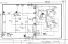
I'm working on an organ with some solid state amplifiers that seem to have output transformers on them. One of the amplifiers is working okay but the other is making a lot of rushing water, flapping and crackling noises and doesn't output audio. I plan on rebuilding it but I wanted to know how it differs from conventional solid state amps and if there is anything special I need to look out for....
 

Attachments

  • Conn-553-Amp-Schem.jpg
    Conn-553-Amp-Schem.jpg
    74.5 KB · Views: 104
Register to hide this ad
I'm not so sure that either "totem pole" or "conventional" is defined well enough to talk about the differences.

I can tell you that transformer T1 takes the audio signal at the emitter of Q902, and both "phase splits" the signal and isolates any DC bias, to prepare the signal for input to the two power output transistors, Q903 and Q904. It looks like the output transistors are biased very much "class B" - virtually zero idle current. The output point of the amplifier (B8 or A2 terminal labels) seems to be DC-coupled, so looking at the DC voltage at that point is a useful diagnostic check - it should be close to zero volts DC.

What strikes me as really odd is that there is a DC-coupled negative feedback loop from the amplifier output to Q901's emitter circuit. The feedback should help make the pure-class-B configuration produce less distortion, mind you - but I'm baffled as to why the loop would be DC-coupled.

I don't know if this has been any help at all. If this were on my bench, I'd probably start with some signal tracing, seeing if an audio input at terminal label A10 made it to Q901's collector (with some amplification along the way), then to the emitter of Q902, to the bases of Q903 & Q904, and finally to the amplifier's output point.

Regardless of what I found there, I'd probably want to check the DC bias on all transistors, seeing if the DC voltages were in the ballpark of what the schematic says.

Making a guess at how old this organ must be, electrolytic capacitors C901, C902, and C903 have to be suspect. (Many AKers would say to replace them, full stop.) C901 in particular, would tend to reduce the gain of the amplifier by a lot if it deteriorated.

Good luck,

chazix
 
Could be a failing transistor

A possibility, for sure. Reminds me to mention: at least the output transistors are germanium parts. Doesn't necessarily make them a lot more likely to be the problem, but it might be tricky to find replacements if needed.
 
Thanks for your help and your detailed explanaition. It is very early. The Organ is from around the mid 70's - I'd say the design of the module is even earlier though... I will definately be replacing the capacitors. Though would it be safe to replace the 250uF with a 220uF due to tollerances in caps or not?

Reminds me to mention: at least the output transistors are germanium parts. Doesn't necessarily make them a lot more likely to be the problem, but it might be tricky to find replacements if needed.
I had been looking into trying to get replacements and thought about replacing with Silicon transistors instead. Would that be a problem changing from germanium to silicon?

I've tried to find something in the ball park for all three and the best oens I have found so far are:

2N2926 - BC33825TA (Fairchild)
2N3405 - 2N5210BU (Fairchild)
DTG110 - I found a cross reference to MP110 which I then used to pick this transistor... 2N6051

Would really appreciate some guidance to see if these will work as replacements... :idea:
 
safe to replace the 250uF with a 220uF due to tollerances in caps or not?

I'm just going to admit that I'm not sure what role the original 250 plays. I'd guess it's not critical, though, so I think either a 220 or 270 replacement would be fine.

Would that be a problem changing from germanium to silicon?

I think it would be a bit of a problem, in that it would make the class B crossover notch problem even worse.

DTG110 - I found a cross reference to MP110 which I then used to pick this transistor... 2N6051

2N6051 is not only silicon, but a Darlington type. It would want an even higher base bias voltage before it would begin to conduct, which would lead to even more crossover notch.

Lots of AKers have a big problem with NTE parts, but if I wanted to replace this amp's output transistors, I think I'd use NTE121.

(I'd better get to my day job, so I haven't looked at the other transistor picks. If it was me, I wouldn't replace any transistors at all until/unless I believed them to be defective.)

Cheers,

chazix
 
2N6051 is not only silicon, but a Darlington type. It would want an even higher base bias voltage before it would begin to conduct, which would lead to even more crossover notch.
Sorry, I must've picked the wrong transistor from my list... I'll try to find the original one I found...

I think it would be a bit of a problem, in that it would make the class B crossover notch problem even worse.

AFAIK, the amp is biased with fixed resistors so could I get around this problem by re-biasing the amp?

If it was me, I wouldn't replace any transistors at all until/unless I believed them to be defective.)

I agree, I started looking at transistors just in case but hopefully replacing the capacitors will sort things out.

Could the 250uF be used in relation to prevent oscillation? I might have completly the wrong idea...
 
AFAIK, the amp is biased with fixed resistors so could I get around this problem by re-biasing the amp?

I don't see why that wouldn't be doable, though it might involve a little experimentation. I would think you'd want to end up with the bias such that there is still some crossover notch, but only as much as there was with the germanium parts. (I think it would be risky to aim for eliminating the notch by having a positive static bias current, since there's nothing except the emitter resistors to counter thermal runaway.)

Could the 250uF be used in relation to prevent oscillation? I might have completly the wrong idea...

I think it's plausible. It is part of another feedback path around Q901 & Q902, and that opens the possibility of oscillation depending on phase response. I'm definitely not clever enough to be sure what the overall response is supposed to be. But, as I think you were alluding to, cap tolerances were pretty loose in the era - so, I still think it's unlikely to be a critical value.
 
Well that didn't go so well....

I have one of these amps that is working and one that isn't so I compared readings from the working one. All the voltages seemed to be near enough to each other and the schematic. The only slight exception was on the collector of Q904 which should be 0V - came out at 332mV on the good amp and 243mV on the bad amp. The second exception was the Base of Q903 which should be 60mV - that came out at 350mV on the good amp and 238mV on the bad amp.

I decided to change the capacitors but only on the bad amplifier. I tested them as I removed them and both 50uF caps were around 65uF. I replaced these with 47uF which measured around 50uF. I then changed the 250uF capacitor. It read 290uF when tested and I replaced this with a 220uF.

I powered it up and started taking voltage readings which all seemed not to have changed but then R916 started to smoke! :eek:

I quickly powered the amp down and checked around and found that the components around Q902 and the transistor itself were quite warm.

My initial thought is that 220uF was a bit too low and that maybe the amp broke into oscillation...
I could be wrong but I thought it might be likely that C905 was allowing high frequencies to pass through to ground via R916 but more than R916 could take so it was overheating?

I think I'll order up some 250 or 270uF caps and see what happens - I don't think the 47uF capacitors were to blame but if anyone thinks otherwise let me know. Would appreciate your thoughts on where to go from here.
 
Bummer!

I agree that the amp must have been oscillating. To overheat R916, I think it must have been a relatively high-frequency oscillation.

The value of the nominally 250uF cap affects a LOW frequency turnover point. For frequencies that are much above about 5Hz, the value of R907 should be dominant. So, that isn't the first thing that would draw my suspicion.

Not that I have anything in the way of a solid suspicion, though. I think it would be worth looking at power rail bypassing (it's true that would be expected to affect both channels, but on the other hand, the bad channel might now have more gain than the good one thanks to the replaced caps), and grounding integrity (yes, R681, and all you black wires, I'm looking at YOU).

It also occurs to me that the DC voltages you checked would probably look OK even if Q903 and/or Q904 have failed open-circuit. I don't know how to predict what that would do to the rest of the amp circuit, but it couldn't hurt to check their base-collector junctions with an ohmmeter. (The base-emitter junctions are pretty much shorted by the transformer windings and the 2.2 ohm resistors, so you won't be able to tell much about those with an ohmmeter unless you do some disconnecting.)

It would probably be wise to use a "dim bulb tester" for further power-on testing. An oscilloscope would probably be a good friend to have, too.

chazix
 
I have a scope that I get hooked up in the next few days - I left it with the rest of the organ! I do have a DBT but this amplifier runs alongside a regulated power supply... which I have just realised looking from the full schematic.. I can disconnect... so that's a help. it was on a DBT this time but the regulated power supply board was drawing so much power I had to have a high powered bulb in.

Q903 and Q904 do unsolder quite easily and so I could remove them and test them... they are TO-3 with the wires soldered directly onto the legs...

I agree that the amp must have been oscillating. To overheat R916, I think it must have been a relatively high-frequency oscillation.

The value of the nominally 250uF cap affects a LOW frequency turnover point. For frequencies that are much above about 5Hz, the value of R907 should be dominant. So, that isn't the first thing that would draw my suspicion.

Not that I have anything in the way of a solid suspicion, though. I think it would be worth looking at power rail bypassing (it's true that would be expected to affect both channels, but on the other hand, the bad channel might now have more gain than the good one thanks to the replaced caps), and grounding integrity (yes, R681, and all you black wires, I'm looking at YOU).

I have ordered some 270uF capacitors along with a replacement resistor (and some spares) for R916. I could test the ground(black wires) and R681... and maybe R907 just to be sure...at 220uF what would the low frequency turnover point be? Could it be that the new capacitors gave the amp enough gain to break into oscillation wheras the old ones gona high enough that it lacked the gain to start oscillating?

What do you mean by power rail bypassing?
 
I just tried disconnecting the regulated power supply for the organ but I still get a large glow on a 100W bulb... there are some parts I can't disconnect like ballast resistors... I looked up power rail bypassing and thought it might help if you could see the whole schematic so I've attached that.

Taking C-B ohmeter readings with them still in circuit...
Q903 - B to C: 162R C to B: 63.4R
Q904 - B to C: 137R C to B: 50.2R

Compared to good amplifier...
Q903 - B to C: 146R C to B: 50.4R
Q904 - B to C: 146R C to B: 58R
 

Attachments

  • Conn-553-Amp-Schematic.jpg
    Conn-553-Amp-Schematic.jpg
    86.8 KB · Views: 7
Last edited:
Time to apologize for loose terminology...

By "turnover", I was using a very dodgy hand-wave about how the combination of R907 and C903 would act if they we a standalone simple 1-pole filter. At 250uF, this imaginary standalone filter would have a 3dB point of 4.7Hz, versus 5.3 Hz with 220uF. So, even though this is way too simplistic to tell us about how the parts affect the overall response of the real circuit, I think it's safe to say that the value of C903 should make little difference at frequencies that are much higher than 5Hz.

I perhaps shouldn't have used "bypassing" - the concept that's important is that the DC power rails should have a low AC impedance across a wide frequency range. I assume there are some big-ish power supply filter capacitors, and they are probably doing their job at low-ish frequencies (or else you'd be hearing line-frequency hum). But they might be deteriorated to the point where they're not very effective at higher frequencies. They may or may not be "bypassed" with smaller caps meant to be effective at higher frequencies - I don't get a clear enough image of the overall schemo to be sure - but if they are, the smaller caps might also be suspect.
 
Ok, I understand a bit more now, thanks. I think I did understand what you were getting at. The main filter caps in the power supply that feed the amps have been replaced..... however C921 and C622 (300uF @ 35V) have not been changed as far as I remember.. I changed the rest of the power supply caps a few years ago. Even though the second amplifier works, do you think those two capacitors could be causing the oscillation?

The readings of the transistors above look a little out of balance compared to the good amplifier...

For some reason the schemo doesn't seem to look great on the viewing. If you download it, it might look clearer? The original file on my PC looks fine when I enlarge it on the PC.
 
Last edited:
for experimentation with bias, the schematics of the Rogers Ravensbourne amp are to be found on the internet, it uses silicon transistors and it has trimmer resistors.
Myself I did not have a clue to what bias it had to be set, I just guessed a "reasonable" bias (forgot how much) refurbishing this amp.
Replacing output transistors, I think it is mandatory have them paired/from the same production batch, which fortunately usually is the case buying from a big supplier.
 
Well the replacement 15 Ohm resistors have arrived along with the 270uF capacitors... where would it be best to go from here? Taking the transistors out of circuit and testing hfe and continuity?

I might end up changing to silicon if there is a problem as re-biasing the amplifier shouldn't be too difficult. So long as I can find what is causing this oscillation... would the scope be able to see this clearly?
 
The B-C junction measurements show at least some forward/reverse ratio, which would make me think the output transistors are OK. (On reflection, it occurred to me that at least one of them had to be working, or else the magnitude of the oscillation probably wouldn't have been enough to toast R916.)

I think I'd power it up with a DBT and look at the oscillation with the 'scope. First, check that it does indeed still oscillate in the DBT scenario. Then look for AC signal, at the oscillation frequency, on the power supply terminals of the amp board. My guess is that you'll find some on the high-power supplies, A1 and A7. But what I think would be more interesting, and perhaps more likely to be related to the cause of the problem, are the lower-power supplies, A5 and A8. I think it's reasonable to expect the low-power supplies to not show any oscillation-frequency AC. If they do, I think I would try connecting a modest-sized filter capacitor between their terminal and a ground terminal on the board to see if that stops the oscillation. If you've still got some new 50uF caps, and they have a voltage rating greater than 30V, they should be good for this experiment.

Best to work quickly, of course, and remove power during "think times". I would leave the old already-toasted R916 in place for this testing, unless it is so deteriorated that its value is way off. It's likely to suffer more abuse during testing.
 
Thanks, the only problem with the DBT is that the power supply for the amps is part of the organ power supply and I'm still trying to isolate it enough so that only the amp boards are running - at the moment the power supply pulls a lot of power - enough to make a 100W lightbulb glow quite a bit to the point I don't know if the DBT is offering much protection to the amp.... I'll try to isolate some more parts of the power supply though and try and sort that out.

Apart from that, I have plenty of capacitors in my little stock so once I get my scope back tomorrow, hopefully I can start to advance into looking for problems... R916 is still reading at 15 Ohms so I can leave it in - although I might lift it away from the board... just in case... I think it's already left some singe marks... :smoke:

Taking a look at the psu rectifier diodes... I think these could be Germanium too... if that is any help - I've heard they might be less reliable than newer silicon ones. To check for oscillation in the amp agian, I'm guessing that I need to start by probing around R916 for starters?
 
I think R916 is a victim rather than a culprit. I think insufficient filtering in the power supplies is the place to look first - if only because that's the only reasonably "easy" answer that I can think of.

If DBT power-up isn't practical, you might consider removing the case screws from the output transistors, thereby disconnecting their collectors. With luck, that will keep the oscillation power level low enough so that there won't be any risk of follow-on damage. This configuration should still keep all the feedback loops intact (at least, the intentional ones) - but it's possible that the oscillation won't happen.
 
Hmm, another "on reflection" correction: With my suggestion of disconnecting the output transistor collectors, there will in fact be little or no signal transfer from the transformer secondaries to the amplifier output point, so one of the feedback loops will be broken. My guess is the amp won't oscillate in this configuration. (Though if it does, it would help narrow down the possible causes. Could be quite a stroke of good luck.)

Still might be worthwhile doing the collector disconnection, though. Assuming it kills the oscillation, it would allow the amp to be powered up with less concern for things getting overheated. The primary-side transistors have their own local feedback loop, so I would expect them to still function as an amplifier, even with the global feedback loop broken. If you can arrange for there to be an input signal, you could 'scope how much gain there is between the amp input and Q902's emitter. Best make it a small input signal, because I'd expect the gain to be as much as 280.
 
Back
Top Bottom