• The move to the new server is done. There are some software and database maintenance updates in process. This has us passing the hat around to help out. We appreciate any donations. Seriously, even a dollar helps. The payment page may be found here - https://www.audiokarma.org/support.html

Help identifying this amplifier design - Totem Pole?

Okay, thanks for your replies - I'll take on board what you've said and connect the scope up and audio generator... without the main output transistors at first. Would I see oscillation on the amplifier output and on the transformer primary?

I'll test the power supplies first - I can do that with the amp disconnected.
 
If the amp oscillates with the output collectors disconnected, I'd expect to see very little at the output, but plenty at the transformer primary terminal that's connected to the emitter of Q902. The other side of the primary, that's connected to C902, should have very little.
 
Well I've found a few interesting things. I started probing the power supply and the collectors of the output transistors and found a big sawtooth wave on Q903... I took a look in the power supply and found a similar sawtooth on the scope at capacitors C920, C921 and C924. I need to verify this though by probing on the other points that these power supplies run into on the amplifier.

I then disconnected the collectors of Q903 and Q904 and put the probe onto the emitter of Q902. The resistor didn't smoke when it was powered on but I could see a small negative blip on the scope and heat building up in R908. After a minute or so, the scope started to jump and flicker showing voltage spikes and other random messy small waveforms on the emitter of Q902.

Just to confirm. I tried exchanging the section the amp with Q902 on it with the section from the good amp and tested that one. (The amplifier is in two sections) The problem followed the bad amps Q902. With the good amplifier's Q902,903 and 904 in place, there was no oscillation or negative blip - just a tiny ripple.

Correct me if I'm wrong, but I think this points to Q902 being the culprit... however the power supplies having such a large sawtooth compared to the other supplies to the organ worries me slightly.... but it only does it when it is under load - ie when I connect the amplifier to the power supply assembly.... maybe I'm making something out of nothing?

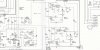
I marked out on a schematic of the PSU where I had a clean power supply (green) and where I found a sawtooth (red). I've already changed these capacitors with the exception of C921 and C922...
 

Attachments

  • Conn-553-PSU-Schem-1.jpg
    Conn-553-PSU-Schem-1.jpg
    71.4 KB · Views: 9
I don't think I'd worry about the sawtooth at these two points:

Q903 collector / C924 - this is the high-power -30V supply, apparently wired in gray

C920 - this is the high-power +30V supply, apparently wired in yellow. (It supplies Q904's emitter through one of the 0.47 ohm resistors.)

I think the sawtooth you're seeing at the above points is the "ripple" that's usual with a simple rectifier/capacitor power supply. The time period between the sawtooth peaks, if you know how to determine that from the scope, should be 8.3 milliseconds. If that is true, it's pretty good evidence that the rectifiers are OK. Given that (I think) you've already replaced C920 and C924, I think whatever ripple still exists would be normal.


It's less clear whether to expect to see ripple on C921. This is the +29V supply, apparently wired in brown. My take it that it's intended to be a slightly-lower-power, slightly-better-filtered supply (in comparison to the high-power +30V supply). As far as what I can see, it needs to supply around 15 milliamps to each of (two?) amplifiers. From that and the capacitance of C921, I guess I'd expect to see a little less than 1V peak-to-peak of sawtooth on C921. If that is the case, and if you're not hearing excessive hum from the good amplifier, I'd say there's no problem here.


Some warming of R908 would be expected in normal operation. It needs to dissipate around 1/4 watt. I wouldn't expect it to get warm enough to be uncomfortable to touch.


I do think that, if the scope shows much of anything happening at the emitter of Q902 when there's no signal applied, Q902 itself is probably the top suspect. And if I understand what you did with exchanging sections, I think there's plenty enough evidence to try replacing Q902. It looks like 2N3405s might still be an active part number from Central Semi, so there might a chance of getting an exact replacement, but I think it's a very long shot.

In a similar application as Q902's, some pretty smart AKers have chosen 2SC3902T (available from Mouser, probably other suppliers), but be aware that this part has different packaging and a different lead arrangement. Also, if the transistor is supposed to be bolted to a heat sink, I believe you will need an insulator for the 2SC3902T.


Nice going with your trouble-shooting!

 
Thanks, :thumbsup: I'll leave the sawtooth ripple for now. So with regards to replacing Q902, I had already looked into a cross reference and I found that BC639 was mentioned as an adequate replacement. I have also just recently replaced a BC639 in a circuit for a KSC3503. Would this work with the amp as I have a few of these already. It does have to be fixed to a heatsink but I do have some insulators if I need them. I took a look at the specs for KSC3503 and it looks like maybe the Ic would be too low but I could do with some help on clarifying this - if this would work... :idea:
 
The specs I found show both KSC3505 and 2N3045 being good for 100mA Ic, so my take is there's no problem there. I think it would be best if your KSC3505s were from the highest beta grade, but it's not a make-or-break thing.

As usual, I have to correct myself, though I don't think it's about anything too crucial: I goofed the math for the current in the Q902 circuit. It's closer to 40mA. In turn, that means that R908 will be dissipating more like 2W, so it just might get too hot for comfortable touching in normal operation. And, the ripple on C921 would probably be more like 2V peak-to-peak.
 
Thanks again for the correction - R908 does get hot on both of the amps so I took it as normal but good to know for sure! Just checking that you meant to type 2N3405 isntead of 2N3045?
 
Well I put a KSC3503 in and the case is completely insulated. I fitted it in updaise down which made the leads line up ECB as the old transistor had done. Soldered it in and powered up and no strange scope signals.

I tried putting a sinewave throughn and got the halves of the signal out of the output transistors so everything seems to be all ok so I will put it back in to test on the organ and let you know how it goes - looks good so far though! :thumbsup:
 

Attachments

  • 20160303_215750.jpg
    20160303_215750.jpg
    70.4 KB · Views: 5
  • 20160303_215743.jpg
    20160303_215743.jpg
    89.8 KB · Views: 6
  • 20160303_210911.jpg
    20160303_210911.jpg
    74.2 KB · Views: 6
Sweet! It's been fun trying to help fix it, and now I hope you or someone has even more pleasure from playing it!
 
Well I just have to plug it back into the organ to test now. But if you can hang in there with me a little longer... I was checkign through the regulated supplies and found that the -5.5V supple is down to -2.5V... I tried adjusting it but the highest I can get it is -3.2V. I'm gonna take a look... Seems a simple circuit that takes a -12V supply and through a combination of transistors and a 4.3V zener gives you the -5.5V supply.
 
Nice catch. That regulator isn't captured on the P/S jpg posted earlier, but if the regulator's power transistor is configured as an emitter follower (that is, if the -5.5V is supposed to come from the emitter of the pass transistor), then one possible culprit would be an open collector junction.

I'm assuming that you already checked that the zener is running pretty close to its nominal 4.3V.
 
I've attached a section with the power supply in. I'm about to check the zener now, but thanks for the tip!
 

Attachments

  • Conn-553-PSU-section-1.jpg
    Conn-553-PSU-section-1.jpg
    61.9 KB · Views: 6
Huh! I guess I should have expected that the regulator would be a little different from what I'm used to seeing, just like everything else...

Anyway, my suggestion to check the zener voltage doesn't make much sense, the way the regulator is designed. If the output of the regulator is only -3.2V, then the zener shouldn't be conducting at all. What does make sense is to check whether the zener (or that cap that parallels it) is shorted.

I still wouldn't bet against the pass transistor having failed open-collector.

Could be that something downstream is trying to draw too much current, too. In that case, I would expect the pass transistor to be running pretty warm, though it's hard to guess what's normal.
 
Well, I can't tell if the zener is working properly.. there is only 3V present on the zener (I adjusted the -5.5 supply from -2.5 to -3 before I started).

I took some measurements and voltages inside the regulator seem to be a bit down...
E C B
Q926 -3.63 (-5.5) -12.8 (-12.4) -4.27 (-6.1)
Q927 -3 (-5.4) -12.8 (-12.4) -3.63 (-5.5)
Q928 -1.5mV (0) -4.2 (-6.1) -0.62 (-0.57)

I'm not so familiar with the term emitter follower.... but I think Q926 and Q927 are doign that. Perhaps it does look as though Q926 or Q928 are failing? I checked R987 and R988 just to make sure and they seem to read as 11k Ohm and 1k Ohm respectively.

Might the small presence of voltage on Q928's emitter indicate it is bleeding the missing voltage away?
 
Well, the voltages in post 36 sure look like something is driving Q928 into conduction, and it shouldn't be, with the regulator's output toltage being too low to make the zener conduct. So, I'm leaning toward a shorted zener or the cap across it.
 
The -14.5V supply outputs -14.9 so that would mean the emitter of Q932 will be -14.9 also, won't it?
 
Back
Top Bottom