Hi everyone,
I have lately been building a number of small, cheap DIY devices meant as soldering practise for beginners. But now that I've built them and have seen them work, I'd also like to understand how they work. And just as I was a complete noob with a soldering iron when I started on this journey, I am a complete noob when it comes to electronics. I am familiar with physics and electricity in general, having received a technical education, but my specialty is software, not hardware. I do have a basic understanding of what various components do, and how they're supposed to work in isolation, but my ability to read a circuit (let alone to design one myself) is extremely basic. One might say I'm at that level where I know just enough to be dangerous.
I'm now doing my best to learn what I should have learned a long time ago.
So, here's the device I'm currently trying to figure out. I chose to start with the one that seemed the simplest of them all.
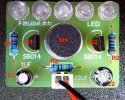
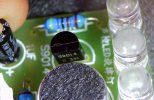
It has a microphone and a row of five LEDs. Whenever the microphone detects a sound, any sound, the LEDs light up.
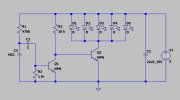
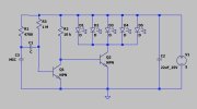
It works perfectly. But I also want to know how it works, and why. And for this reason I tried to draw a schematic in KiCad, based on the tracks that I could see on the PCB.
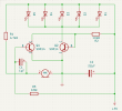
There is a caveat, though. I only drew the connections that I could see. I have no idea if the PCB has a second layer that I can't see. Given the apparent simplicity of the design and the very low price of the thing, I think this is unlikely. But I guess it's not impossible.
The problem is, the schematic doesn't make sense to me. Looking at it, it seems to me the thing cannot possibly work. And yet, we know it does.
First, I don't get why the LEDs are off when there's no sound and the microphone isn't doing anything.
The anodes of the LEDs are permanently connected to 5V through the direct connection on the right-hand side of the schematic. The only thing that keeps them from lighting up (and blowing for that matter, since there's no resistor in series with them on that side) is the Q2 transistor being off. But why should it be off? Its base is connected to the positive rail through a 10kΩ resistor. The base-emitter "on" voltage of an S9014 transistor is around 0.6V, reaching saturation at around 1V. So, if the transistor draws 1V from the 5V supply, then the 10kΩ resistor is left with 4V. This means the current through the resistor (and consequently through the base of Q2) is 4/10.000 = 0.4mA. The gain of an S9014 is at least 60, with a typical value of 260. Even with a gain of 60, that would mean a collector-emitter current of 0.4*60 = 24mA, which should cause the LEDs to glow at full brightness.
But they don't. So I'm clearly missing something. The above reasoning must be wrong. But how?
Maybe it has something to do with the C2 capacitor? That looks like a smoothing capacitor to me, though I fail to see why such a high capacitance should be needed for this purpose. If smoothing were the only reason for the existence of that capacitor, then I would expect it to be a small ceramic one. So maybe it serves a different purpose?
Now, let's take a look at the left side of the circuit.
The base of Q1 is connected to power via a 1MΩ resistor, which is too big to allow any meaningful current to pass through the base. So, Q1 is off.
When the microphone detects a sound, it will generate a small current, whose DC component will be filtered out by C1, so that only the sound signal will reach the base of Q1. That signal, albeit small, may be enough to cause Q1 to turn on. But what happens when it turns on? A current will start to flow from its collector to its base, "stealing" from the current that currently goes from the 10kΩ resistor to the base of Q2. In other words, the more Q1 conducts, the less Q2 will conduct. That should cause the LEDs to turn dimmer, not brighter.
So again I am missing something, and again I can't figure out what.
My third dilemma is that C1 is a polarized capacitor, but its cathode is connected to a positive voltage supply. Sure, with a 1MΩ resistor in series the current is very low, but still... Won't this be a problem? Electrolytics don't like to be fed backwards.
And my fourth dilemma is how the LEDs are protected. An LED must always be powered through a series resistor, but in this case they aren't. R1 isn't properly in series with the LEDs, because the LEDs receive 5V directly from the source, on the right-hand side of the circuit. R1 only limits the current delivered by the microphone, which I imagine is only a tiny part of what the LEDs are receiving. Besides, isn't 4.7kΩ too much? For LEDs at 5V I would expect something in the vicinity of 220 - 330Ω. That is, unless the microphone delivered a much higher voltage than 5V. But I don't think that's the case. Is it?
What am I missing? A lot of things, I'm guessing. Or maybe a tiny one that just happens to turn everything around?
Thank you.
I have lately been building a number of small, cheap DIY devices meant as soldering practise for beginners. But now that I've built them and have seen them work, I'd also like to understand how they work. And just as I was a complete noob with a soldering iron when I started on this journey, I am a complete noob when it comes to electronics. I am familiar with physics and electricity in general, having received a technical education, but my specialty is software, not hardware. I do have a basic understanding of what various components do, and how they're supposed to work in isolation, but my ability to read a circuit (let alone to design one myself) is extremely basic. One might say I'm at that level where I know just enough to be dangerous.
I'm now doing my best to learn what I should have learned a long time ago.
So, here's the device I'm currently trying to figure out. I chose to start with the one that seemed the simplest of them all.
It has a microphone and a row of five LEDs. Whenever the microphone detects a sound, any sound, the LEDs light up.
It works perfectly. But I also want to know how it works, and why. And for this reason I tried to draw a schematic in KiCad, based on the tracks that I could see on the PCB.
There is a caveat, though. I only drew the connections that I could see. I have no idea if the PCB has a second layer that I can't see. Given the apparent simplicity of the design and the very low price of the thing, I think this is unlikely. But I guess it's not impossible.
The problem is, the schematic doesn't make sense to me. Looking at it, it seems to me the thing cannot possibly work. And yet, we know it does.
First, I don't get why the LEDs are off when there's no sound and the microphone isn't doing anything.
The anodes of the LEDs are permanently connected to 5V through the direct connection on the right-hand side of the schematic. The only thing that keeps them from lighting up (and blowing for that matter, since there's no resistor in series with them on that side) is the Q2 transistor being off. But why should it be off? Its base is connected to the positive rail through a 10kΩ resistor. The base-emitter "on" voltage of an S9014 transistor is around 0.6V, reaching saturation at around 1V. So, if the transistor draws 1V from the 5V supply, then the 10kΩ resistor is left with 4V. This means the current through the resistor (and consequently through the base of Q2) is 4/10.000 = 0.4mA. The gain of an S9014 is at least 60, with a typical value of 260. Even with a gain of 60, that would mean a collector-emitter current of 0.4*60 = 24mA, which should cause the LEDs to glow at full brightness.
But they don't. So I'm clearly missing something. The above reasoning must be wrong. But how?
Maybe it has something to do with the C2 capacitor? That looks like a smoothing capacitor to me, though I fail to see why such a high capacitance should be needed for this purpose. If smoothing were the only reason for the existence of that capacitor, then I would expect it to be a small ceramic one. So maybe it serves a different purpose?
Now, let's take a look at the left side of the circuit.
The base of Q1 is connected to power via a 1MΩ resistor, which is too big to allow any meaningful current to pass through the base. So, Q1 is off.
When the microphone detects a sound, it will generate a small current, whose DC component will be filtered out by C1, so that only the sound signal will reach the base of Q1. That signal, albeit small, may be enough to cause Q1 to turn on. But what happens when it turns on? A current will start to flow from its collector to its base, "stealing" from the current that currently goes from the 10kΩ resistor to the base of Q2. In other words, the more Q1 conducts, the less Q2 will conduct. That should cause the LEDs to turn dimmer, not brighter.
So again I am missing something, and again I can't figure out what.
My third dilemma is that C1 is a polarized capacitor, but its cathode is connected to a positive voltage supply. Sure, with a 1MΩ resistor in series the current is very low, but still... Won't this be a problem? Electrolytics don't like to be fed backwards.
And my fourth dilemma is how the LEDs are protected. An LED must always be powered through a series resistor, but in this case they aren't. R1 isn't properly in series with the LEDs, because the LEDs receive 5V directly from the source, on the right-hand side of the circuit. R1 only limits the current delivered by the microphone, which I imagine is only a tiny part of what the LEDs are receiving. Besides, isn't 4.7kΩ too much? For LEDs at 5V I would expect something in the vicinity of 220 - 330Ω. That is, unless the microphone delivered a much higher voltage than 5V. But I don't think that's the case. Is it?
What am I missing? A lot of things, I'm guessing. Or maybe a tiny one that just happens to turn everything around?
Thank you.
Last edited: