

You are using an out of date browser. It may not display this or other websites correctly.
You should upgrade or use an alternative browser.
You should upgrade or use an alternative browser.
Help me understand this schematic
- Thread starter Vlad Soare
- Start date


AliExpress is a great source for this kind of stuff, but luckily I can also find it locally. In the few instances when instructions are provided, they are always in Chinese only, so I assume most (if not all) of it comes from AliExpress.somewhat OT - what are the kits for practicing soldering you have found? i assume AliExpress?
For instance, this is my latest acquisition. Ordered yesterday, received today. I haven't built it yet. EMag is a big online retailer around here. A sort of local AliExpress. 17 lei is about 3.7 US dollars.
Apart from the colour of the PCB, it seems to be exactly this one:
Last edited:
You can see more examples of such small DIY kits in this thread, where I described my journey into the art of soldering. Videos of some of the finished stuff are linked in post #21.
Okay, now that the sound detector is clear, I thought I'd move on to my next project. This is the very first one I built, and I chose it because it seemed to be quite simple, though I quickly discovered that it was anything but.
It's an LED heart that pulsates:
The problem is, it uses an LM358P chip, which Google tells me is a pair of op-amps. I had heard of op-amps, as they're so frequently discussed on these forums, but I had no idea what they were supposed to do and how. So I read a bit about them and understood their basic working principle, and I have also built a small non-inverting amplifier circuit on the breadboard, using the very chip from this heart, to check the voltages and see how the amplification works.
But this particular case seems to be a bit more complicated, so again I need to appeal to you for help.
This is the schematic, as figured out by myself based on the tracks on the PCB.
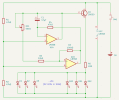
The LED part is simple enough. They're powered through a 22Ω resistor, which for 22 LEDs in parallel means just slightly over 10mA for each one. That's perfect. And this is just the maximum current; they won't always receive this much.
But I can't figure out exactly how the pulsating part works.
At first I thought that perhaps the op-amps modulate the current through the base of Q1 somehow. But now I think this is unlikely. I think what causes the base current to fluctuate is actually the C1 capacitor charging and discharging.
I suspect that the first op-amp, labelled U1A, alternately delivers either full voltage (in which case the base current of Q1 slowly increases while the capacitor is charging), or no voltage at all (in which case the base of Q1 continues to be powered by the slowly discharging capacitor).
U1A seems to be set up not as an op-amp per se, but as a simple comparator. A fixed 2.5V reference (because R1 and R2 form a voltage divider and have equal resistance values) on the non-inverting input is compared with whatever voltage is received at the inverting input. If the latter is lower than 2.5V, then U1A delivers 5V to the transistor, and the capacitor starts charging. If it's higher than 2.5V, then it delivers 0V to the transistor, and the capacitor starts discharging.
Am I right so far?
But now I'm blocked. I can't figure out how the voltage at the inverting input of U1A is regulated. Obviously, it's the second op-amp, U1B, that's responsible for this. But I'm not sure I understand how it does it.
U1B doesn't look like a simple comparator, because it uses feedback. So at first glance it doesn't look like it outputs all or nothing, like U1A does, but rather a varying voltage. But it's strange that it receives feedback at its non-inverting input. All the examples that I've seen of op-amps used as amplifiers, be they inverting or non-inverting, were receiving feedback on the inverting input. So maybe U1B, despite using feedback, isn't actually set up as an amplifier, but still as a comparator?
I'm imagining it works somewhat like this:
It's an LED heart that pulsates:
The problem is, it uses an LM358P chip, which Google tells me is a pair of op-amps. I had heard of op-amps, as they're so frequently discussed on these forums, but I had no idea what they were supposed to do and how. So I read a bit about them and understood their basic working principle, and I have also built a small non-inverting amplifier circuit on the breadboard, using the very chip from this heart, to check the voltages and see how the amplification works.
But this particular case seems to be a bit more complicated, so again I need to appeal to you for help.
This is the schematic, as figured out by myself based on the tracks on the PCB.
The LED part is simple enough. They're powered through a 22Ω resistor, which for 22 LEDs in parallel means just slightly over 10mA for each one. That's perfect. And this is just the maximum current; they won't always receive this much.
But I can't figure out exactly how the pulsating part works.
At first I thought that perhaps the op-amps modulate the current through the base of Q1 somehow. But now I think this is unlikely. I think what causes the base current to fluctuate is actually the C1 capacitor charging and discharging.
I suspect that the first op-amp, labelled U1A, alternately delivers either full voltage (in which case the base current of Q1 slowly increases while the capacitor is charging), or no voltage at all (in which case the base of Q1 continues to be powered by the slowly discharging capacitor).
U1A seems to be set up not as an op-amp per se, but as a simple comparator. A fixed 2.5V reference (because R1 and R2 form a voltage divider and have equal resistance values) on the non-inverting input is compared with whatever voltage is received at the inverting input. If the latter is lower than 2.5V, then U1A delivers 5V to the transistor, and the capacitor starts charging. If it's higher than 2.5V, then it delivers 0V to the transistor, and the capacitor starts discharging.
Am I right so far?
But now I'm blocked. I can't figure out how the voltage at the inverting input of U1A is regulated. Obviously, it's the second op-amp, U1B, that's responsible for this. But I'm not sure I understand how it does it.
U1B doesn't look like a simple comparator, because it uses feedback. So at first glance it doesn't look like it outputs all or nothing, like U1A does, but rather a varying voltage. But it's strange that it receives feedback at its non-inverting input. All the examples that I've seen of op-amps used as amplifiers, be they inverting or non-inverting, were receiving feedback on the inverting input. So maybe U1B, despite using feedback, isn't actually set up as an amplifier, but still as a comparator?
I'm imagining it works somewhat like this:
- With no power, everything is off (obviously).
- When you turn on the power, U1B has 2.5V at the inverting input and 0V at the non-inverting one. Consequently, its output is 0V, which means U1A has 0V at the inverting input. But U1A has 2.5V at the non-inverting input, which is higher than 0V, so it will output 5V.
- While U1A outputs 5V, the capacitor starts charging and the LEDs turn slowly on, reaching full output when the capacitor is fully charged.
- While the capacitor is charging, the voltage through RV1 and R6 slowly increases, until it gets to 5V.
- Now U1B receives 5V at its non-inverting input, which is higher than the 2.5V that it has at the inverting one, so now U1B outputs 5V.
- This causes U1A to receive 5V on the inverting input, which is higher than the 2.5V that it has at the non-inverting one, so now U1A will output 0V. Now the capacitor starts discharging into the circuit and the LEDs slowly fade.
- While the capacitor discharges, the voltage through RV1 and R6 slowly drops down to 0V. Now the non-inverting input of U1B is again lower than its inverting one, so its output becomes 0V again. And the cycle repeats.
Last edited:

ConradH
Lunatic Member
I think you're about right. Think of it this way. Both opamps are referenced to the voltage at the junction of R1 and R2, about half the supply. U1A is set up as an integrator, so it will charge or discharge C1, depending on the level at its inverting input compared to the fixed non-inverting input. U1B is set up as a comparator. Notice it has positive feedback (R3) that will tend it to swing full on or full off. Its input is the voltage to Q1. As that voltage crosses the halfway point, it will drive U1A to start swinging positive or negative, until U1B flips the other way. Or something like that. The key to all similar oscillators is an integrator that controls the rate and a comparator that controls the direction.
It's precisely this feedback that's not entirely clear to me.Notice it has positive feedback (R3) that will tend it to swing full on or full off.
I understand how feedback works in the context of an amplifier - the op-amp amplifies the difference between its inputs by a factor that's defined by the ratio between the feedback and the input resistors. But here, since the feedback is fed to the non-inverting input, it can't work like that. It seems to me that once U1B swings to full on, from that point on it will continue feeding itself and will never swing back again. Why should it care from that point on whether the voltage through RV1 and R6 drops, if it receives 5V anyway from itself via R3, which will always be higher than the 2.5V reference?

And yet it does eventually swing back, so I must be missing something. And I wouldn't be surprised if it were something really obvious.

Last edited:
ConradH
Lunatic Member
It's a matter of resistor values. The feedback resistor is 100k so it's not that hard to force the input and flip the output state. Look up comparators and hysteresis. You can have a lot or a little. What this really does is give a clean switch, so the opamp output isn't doing a noisy dance at the instant of switching.
ConradH
Lunatic Member
Also, look up ramp generators. Your circuit is at the heart of most of them. They've been important in oscilloscopes, probably TVs and many other things having to do with timing. It's interesting to see what it takes to build a really good one, low leakage currents and capacitors with low dielectric absorption.
In the meantime I read more about op-amps and comparators, and I think I now understand how feedback works.
With no feedback, the op-amp is a simple comparator.
With negative feedback, the op-amp becomes an amplifier. It amplifies the difference between its inputs proportionally to the ratio between the input and the feedback resistors.
With positive feedback, the op-amp becomes a comparator with hysteresis. The amount of hysteresis depends on the ratio between the input and feedback resistors.
Right?
I still have some doubts, though, in regard to how the amount of hysteresis/feedback is calculated. I have found websites and articles describing the formulae, and I understand the basic idea, but I'm not entirely satisfied yet. But this it a topic for another time. I'll try to figure it out myself first.
What still puzzles me about the above circuit is how exactly the capacitor C1 works in this context.
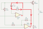
Charging looks straightforward enough. C1 charges through R4, like this:
But discharging doesn't look right to me.
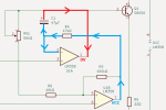
Once U1A has flipped to low and U1B to high, what causes C1 to discharge nicely and slowly through RV1 and Q1, thus turning the LEDs off smoothly and gradually? Why doesn't it discharge instantly via the red path? Why doesn't U1A immediately sink all of C1's charge, since there's no resistance that way?
Actually, why doesn't C1 discharge internally, since its cathode is now positive?
I'm clearly missing something, and I wouldn't be surprised to find it's really obvious, but I just can't figure out what.
With no feedback, the op-amp is a simple comparator.
With negative feedback, the op-amp becomes an amplifier. It amplifies the difference between its inputs proportionally to the ratio between the input and the feedback resistors.
With positive feedback, the op-amp becomes a comparator with hysteresis. The amount of hysteresis depends on the ratio between the input and feedback resistors.
Right?
I still have some doubts, though, in regard to how the amount of hysteresis/feedback is calculated. I have found websites and articles describing the formulae, and I understand the basic idea, but I'm not entirely satisfied yet. But this it a topic for another time. I'll try to figure it out myself first.
What still puzzles me about the above circuit is how exactly the capacitor C1 works in this context.
Charging looks straightforward enough. C1 charges through R4, like this:
But discharging doesn't look right to me.
Once U1A has flipped to low and U1B to high, what causes C1 to discharge nicely and slowly through RV1 and Q1, thus turning the LEDs off smoothly and gradually? Why doesn't it discharge instantly via the red path? Why doesn't U1A immediately sink all of C1's charge, since there's no resistance that way?
Actually, why doesn't C1 discharge internally, since its cathode is now positive?
I'm clearly missing something, and I wouldn't be surprised to find it's really obvious, but I just can't figure out what.
Last edited: