

You are using an out of date browser. It may not display this or other websites correctly.
You should upgrade or use an alternative browser.
You should upgrade or use an alternative browser.
Help Needed w/ Pioneer SX950
- Thread starter Lexx510
- Start date
Yes, please!@Lexx510, if you are interested I can write a summary how I did my one replacement for the STV-4H and what are the tricky parts on that.
There are quite a few ways already posted here at AK, so here you can read my STV-4H workaround.
With this workaround a broken STV 4H is no longer an unobtainable part.
Things you need for sure.
A working DBT, a DMM, several 1n4148, aluminum U-profile, 2 component epoxy clue, red and black heat shrink, one red and black lead at least 2 inch long, check every diode with a diode tester for its voltage of 0.7V.
Tools used. Dremel with small cutting disc, drill 3.5 mm, small file, flat pliers, solder iron
It’s not a big job, and I found it very easy after my first three attempts, if you take your time and follow the given advice. BUT please read the whole procedure FIRST before you start with anything!
The basic for all my six attempts are three 1n4148 in line. With 3 times 0.7V you get 2.1V in total which is very close to the 4 x 0,55V (=2.2V) in the STV-4H.
Before you start with all that work, make a drawing were you can see the position of the anode and cathode soldering points on the pcb. Then draw the original lead routing from that points to the STV and how the STV is mounted.
On my SX-737 the STV was always mounted with the gab downwards and the leads running on the left and right side to the board, making sure they will never get in touch with something else.
But the anode and cathode soldering points are turned by 180° between left and right channel. With the original STV it was no problem, you just turned the varistor and every wire was in the right position. But if you make it my way, you will have to build one for the left side and one for the right side to get a proper replacement. You will understand it better, if you look at the pictures below.
To get my final and “wife approved workaround” I ended up with 5 replicas.
What else do you have to consider. With 3 x 1n4148 the part will get much bigger as the original, but you will get as well a bigger surface for a good contact to the big heatsink.
Next and much important, you have to make sure that none of the open wires will get in contact to the surrounding metal, so take special care on that!
How would I start if I would to it again.
The STV consists out of 3 diodes in line. So you will have with the final part always on one side the anode and on the other side the cathode. As the first step take two diodes, you should be able to find out which side is anode and which is cathode, take the red color lead and solder it to the anode side of one diode and the black to the cathode of the second diode. Then cover the lead on the anode with a red heat shrink and to the same on a second one with a black heat shrink over the lead for the cathode. Push the heat shrink very close to the housing so you have a whole isolation over the lead and apply the required heat with a lighter or what every you want do use. I would NOT recommend a heat gun!
You end up with the first and the last diode, marked with the right color. Now you can take the third diode which will be in the middle, but check the correct direction and twist both leads as close as you want together.
Why should you to that at first step! On my first two tries everything was twisted together, finished with solder and bend for the best position. As soon as I started with the heat gun on the heat shrink, the soldering got soft and everything fall apart. Not good, very surprising! But you will learn your own way. Measure again with a diode tester that you have 2.1V over all three diodes.
Ok, that was the first preparation, leave it as it is, don’t cut any wires and continue with the metal case.
My plan was to build a case with a flat and solid side, to get a very good contact to the heat sink. I bought an aluminum U-profile with 1.5mm thickness and 10mm space between the legs. You can use whatever is at hand, but it should have at least a flat and stable backside for a good heat-contact.
First I drilled the 3.5mm gap for the screw, then cut with the dremel both wings on the side with the hole very close to the bottom as you can see on the picture. The length of the cut must ensure, that you have still enough space for the screw head. It’s up to you which side you bend inside and/or where to you cut off the excessive rest. That is only necessary to keep the epoxy in position.
As an extra isolation, I used a small plastic strip, cut and bend with the help of a hot knife, just to fit to the side off the metal. On one of the picture I have the side wings at full height, but it didn’t look to good. Since the diode didn’t need more than 4-5mm in height, I decided to reduce the sidewalls to get a more handsome look at the end.
After finishing the metal case, you can continue with the final steps.
Take your drawing what you should have prepared as first, decide for which side you will build the STV, place your metal holder on that drawing and but it into the final mounting position. The only but very important purpose for that, you must be sure how the leads have to run without crossing each other after the STV is in the correct position. Maybe you find it helpful to mark at least the red or the black side on the metal case for later.
This information helps you to bend the diodes in position so they fit nicely inside the metal case, make sure that the two ends from the middle diode show upwards and careful take a little solder to both leads before you cut them.
With this preparation done, I mixed a small amount of my two component epoxy-clue, put it on the metal where I later want to position the diode. Not too much, otherwise the glue will run to each open side. Then you can position the extra plastic strips for the side isolation and wait a few minutes until the first layer of clue gets more sticky. After that you will carful place the diodes on the metal frame, recheck again the correct position of the red and black side and position the diodes as you like. You have to make sure, that none of the leads will touch the surrounding metal, the glass housing of the diode is OK. I did tilt the long legs a bit and kept them away. If you find it better for you, put it on tooth sticks or chopsticks, the only reason is to keep it a bit lifted away.
Mix enough epoxy for the second layer and apply it so it will cover the diodes AND the heat shrinked leads. Let it harden long enough and if you find it necessary, apply a third layer on top. As last job, take your DMM set it to resistor and recheck that there is no contact on both wires to the outside metal frame.
That’s it, hope you are successful. In the meantime I have built one for the left and one for the right channel and both work great over the last two months.
Only one last reminder. After you replace the STV-4H with your own rebuild, start the unit with the DBT to make sure you did everything in the right order!! AND follow merlynsky advice for DC offset and bias adjustment.
Here are some pictures from my result.
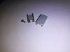

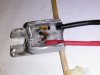
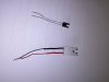
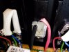
That's a picture how it should never look at the end!! It was my third try
Edit: Diode part number corrected
With this workaround a broken STV 4H is no longer an unobtainable part.
Things you need for sure.
A working DBT, a DMM, several 1n4148, aluminum U-profile, 2 component epoxy clue, red and black heat shrink, one red and black lead at least 2 inch long, check every diode with a diode tester for its voltage of 0.7V.
Tools used. Dremel with small cutting disc, drill 3.5 mm, small file, flat pliers, solder iron
It’s not a big job, and I found it very easy after my first three attempts, if you take your time and follow the given advice. BUT please read the whole procedure FIRST before you start with anything!
The basic for all my six attempts are three 1n4148 in line. With 3 times 0.7V you get 2.1V in total which is very close to the 4 x 0,55V (=2.2V) in the STV-4H.
Before you start with all that work, make a drawing were you can see the position of the anode and cathode soldering points on the pcb. Then draw the original lead routing from that points to the STV and how the STV is mounted.
On my SX-737 the STV was always mounted with the gab downwards and the leads running on the left and right side to the board, making sure they will never get in touch with something else.
But the anode and cathode soldering points are turned by 180° between left and right channel. With the original STV it was no problem, you just turned the varistor and every wire was in the right position. But if you make it my way, you will have to build one for the left side and one for the right side to get a proper replacement. You will understand it better, if you look at the pictures below.
To get my final and “wife approved workaround” I ended up with 5 replicas.
What else do you have to consider. With 3 x 1n4148 the part will get much bigger as the original, but you will get as well a bigger surface for a good contact to the big heatsink.
Next and much important, you have to make sure that none of the open wires will get in contact to the surrounding metal, so take special care on that!
How would I start if I would to it again.
The STV consists out of 3 diodes in line. So you will have with the final part always on one side the anode and on the other side the cathode. As the first step take two diodes, you should be able to find out which side is anode and which is cathode, take the red color lead and solder it to the anode side of one diode and the black to the cathode of the second diode. Then cover the lead on the anode with a red heat shrink and to the same on a second one with a black heat shrink over the lead for the cathode. Push the heat shrink very close to the housing so you have a whole isolation over the lead and apply the required heat with a lighter or what every you want do use. I would NOT recommend a heat gun!
You end up with the first and the last diode, marked with the right color. Now you can take the third diode which will be in the middle, but check the correct direction and twist both leads as close as you want together.
Why should you to that at first step! On my first two tries everything was twisted together, finished with solder and bend for the best position. As soon as I started with the heat gun on the heat shrink, the soldering got soft and everything fall apart. Not good, very surprising! But you will learn your own way. Measure again with a diode tester that you have 2.1V over all three diodes.
Ok, that was the first preparation, leave it as it is, don’t cut any wires and continue with the metal case.
My plan was to build a case with a flat and solid side, to get a very good contact to the heat sink. I bought an aluminum U-profile with 1.5mm thickness and 10mm space between the legs. You can use whatever is at hand, but it should have at least a flat and stable backside for a good heat-contact.
First I drilled the 3.5mm gap for the screw, then cut with the dremel both wings on the side with the hole very close to the bottom as you can see on the picture. The length of the cut must ensure, that you have still enough space for the screw head. It’s up to you which side you bend inside and/or where to you cut off the excessive rest. That is only necessary to keep the epoxy in position.
As an extra isolation, I used a small plastic strip, cut and bend with the help of a hot knife, just to fit to the side off the metal. On one of the picture I have the side wings at full height, but it didn’t look to good. Since the diode didn’t need more than 4-5mm in height, I decided to reduce the sidewalls to get a more handsome look at the end.
After finishing the metal case, you can continue with the final steps.
Take your drawing what you should have prepared as first, decide for which side you will build the STV, place your metal holder on that drawing and but it into the final mounting position. The only but very important purpose for that, you must be sure how the leads have to run without crossing each other after the STV is in the correct position. Maybe you find it helpful to mark at least the red or the black side on the metal case for later.
This information helps you to bend the diodes in position so they fit nicely inside the metal case, make sure that the two ends from the middle diode show upwards and careful take a little solder to both leads before you cut them.
With this preparation done, I mixed a small amount of my two component epoxy-clue, put it on the metal where I later want to position the diode. Not too much, otherwise the glue will run to each open side. Then you can position the extra plastic strips for the side isolation and wait a few minutes until the first layer of clue gets more sticky. After that you will carful place the diodes on the metal frame, recheck again the correct position of the red and black side and position the diodes as you like. You have to make sure, that none of the leads will touch the surrounding metal, the glass housing of the diode is OK. I did tilt the long legs a bit and kept them away. If you find it better for you, put it on tooth sticks or chopsticks, the only reason is to keep it a bit lifted away.
Mix enough epoxy for the second layer and apply it so it will cover the diodes AND the heat shrinked leads. Let it harden long enough and if you find it necessary, apply a third layer on top. As last job, take your DMM set it to resistor and recheck that there is no contact on both wires to the outside metal frame.
That’s it, hope you are successful. In the meantime I have built one for the left and one for the right channel and both work great over the last two months.
Only one last reminder. After you replace the STV-4H with your own rebuild, start the unit with the DBT to make sure you did everything in the right order!! AND follow merlynsky advice for DC offset and bias adjustment.
Here are some pictures from my result.
That's a picture how it should never look at the end!! It was my third try
Edit: Diode part number corrected
Last edited:

Thank you so much!There are quite a few ways already posted here at AK, so here you can read my STV-4H workaround.
With this workaround a broken STV 4H is no longer an unobtainable part.
Things you need for sure.
A working DBT, a DMM, several 1n4148, aluminum U-profile, 2 component epoxy clue, red and black heat shrink, one red and black lead at least 2 inch long, check every diode with a diode tester for its voltage of 0.7V.
Tools used. Dremel with small cutting disc, drill 3.5 mm, small file, flat pliers, solder iron
It’s not a big job, and I found it very easy after my first three attempts, if you take your time and follow the given advice. BUT please read the whole procedure FIRST before you start with anything!
The basic for all my six attempts are three 1n4148 in line. With 3 times 0.7V you get 2.1V in total which is very close to the 4 x 0,55V (=2.2V) in the STV-4H.
Before you start with all that work, make a drawing were you can see the position of the anode and cathode soldering points on the pcb. Then draw the original lead routing from that points to the STV and how the STV is mounted.
On my SX-737 the STV was always mounted with the gab downwards and the leads running on the left and right side to the board, making sure they will never get in touch with something else.
But the anode and cathode soldering points are turned by 180° between left and right channel. With the original STV it was no problem, you just turned the varistor and every wire was in the right position. But if you make it my way, you will have to build one for the left side and one for the right side to get a proper replacement. You will understand it better, if you look at the pictures below.
To get my final and “wife approved workaround” I ended up with 5 replicas.
What else do you have to consider. With 3 x n4148 the part will get much bigger as the original, but you will get as well a bigger surface for a good contact to the big heatsink.
Next and much important, you have to make sure that none of the open wires will get in contact to the surrounding metal, so take special care on that!
How would I start if I would to it again.
The STV consists out of 3 diodes in line. So you will have with the final part always on one side the anode and on the other side the cathode. As the first step take two diodes, you should be able to find out which side is anode and which is cathode, take the red color lead and solder it to the anode side of one diode and the black to the cathode of the second diode. Then cover the lead on the anode with a red heat shrink and to the same on a second one with a black heat shrink over the lead for the cathode. Push the heat shrink very close to the housing so you have a whole isolation over the lead and apply the required heat with a lighter or what every you want do use. I would NOT recommend a heat gun!
You end up with the first and the last diode, marked with the right color. Now you can take the third diode which will be in the middle, but check the correct direction and twist both leads as close as you want together.
Why should you to that at first step! On my first two tries everything was twisted together, finished with solder and bend for the best position. As soon as I started with the heat gun on the heat shrink, the soldering got soft and everything fall apart. Not good, very surprising! But you will learn your own way. Measure again with a diode tester that you have 2.1V over all three diodes.
Ok, that was the first preparation, leave it as it is, don’t cut any wires and continue with the metal case.
My plan was to build a case with a flat and solid side, to get a very good contact to the heat sink. I bought an aluminum U-profile with 1.5mm thickness and 10mm space between the legs. You can use whatever is at hand, but it should have at least a flat and stable backside for a good heat-contact.
First I drilled the 3.5mm gap for the screw, then cut with the dremel both wings on the side with the hole very close to the bottom as you can see on the picture. The length of the cut must ensure, that you have still enough space for the screw head. It’s up to you which side you bend inside and/or where to you cut off the excessive rest. That is only necessary to keep the epoxy in position.
As an extra isolation, I used a small plastic strip, cut and bend with the help of a hot knife, just to fit to the side off the metal. On one of the picture I have the side wings at full height, but it didn’t look to good. Since the diode didn’t need more than 4-5mm in height, I decided to reduce the sidewalls to get a more handsome look at the end.
After finishing the metal case, you can continue with the final steps.
Take your drawing what you should have prepared as first, decide for which side you will build the STV, place your metal holder on that drawing and but it into the final mounting position. The only but very important purpose for that, you must be sure how the leads have to run without crossing each other after the STV is in the correct position. Maybe you find it helpful to mark at least the red or the black side on the metal case for later.
This information helps you to bend the diodes in position so they fit nicely inside the metal case, make sure that the two ends from the middle diode show upwards and careful take a little solder to both leads before you cut them.
With this preparation done, I mixed a small amount of my two component epoxy-clue, put it on the metal where I later want to position the diode. Not too much, otherwise the glue will run to each open side. Then you can position the extra plastic strips for the side isolation and wait a few minutes until the first layer of clue gets more sticky. After that you will carful place the diodes on the metal frame, recheck again the correct position of the red and black side and position the diodes as you like. You have to make sure, that none of the leads will touch the surrounding metal, the glass housing of the diode is OK. I did tilt the long legs a bit and kept them away. If you find it better for you, put it on tooth sticks or chopsticks, the only reason is to keep it a bit lifted away.
Mix enough epoxy for the second layer and apply it so it will cover the diodes AND the heat shrinked leads. Let it harden long enough and if you find it necessary, apply a third layer on top. As last job, take your DMM set it to resistor and recheck that there is no contact on both wires to the outside metal frame.
That’s it, hope you are successful. In the meantime I have built one for the left and one for the right channel and both work great over the last two months.
Only one last reminder. After you replace the STV-4H with your own rebuild, start the unit with the DBT to make sure you did everything in the right order!! AND follow merlynsky advice for DC offset and bias adjustment.
Here are some pictures from my result.
View attachment 1636579 View attachment 1636581 View attachment 1636582 View attachment 1636583 View attachment 1636597
That's a picture how it should never look at the end!! It was my third try
Edit: Diode part number corrected
@pa_200 , do you think something like this would work for the enclosure instead of the aluminum u-profile?
https://smile.amazon.com/Yziss-Alum...rds=aluminum+diode+case&qid=1570591750&sr=8-5
https://smile.amazon.com/Yziss-Alum...rds=aluminum+diode+case&qid=1570591750&sr=8-5
If you want to kill the pioneer!!!
A bridge rectifier is a complete different part, what you need is a varistor and if you look for a replacement of the STV-4H there are only 3 possibilities

But if you mean only the empty enclosure without the parts and you place the 3 x 1n4148 inside, that should work if it fits to the heatsink.
A bridge rectifier is a complete different part, what you need is a varistor and if you look for a replacement of the STV-4H there are only 3 possibilities
- You try to get the broken leads connected again
- You look for a used one out of a donor unit
- You build a new replacement like I did.
But if you mean only the empty enclosure without the parts and you place the 3 x 1n4148 inside, that should work if it fits to the heatsink.
Yes, I should've clarified. I only wanted to use that part for the enclosure, since it might save me some drilling time.If you want to kill the pioneer!!!
A bridge rectifier is a complete different part, what you need is a varistor and if you look for a replacement of the STV-4H there are only 3 possibilities
Do yourself the favor and look for the different use of a bridge rectifier and a varistor!
- You try to get the broken leads connected again
- You look for a used one out of a donor unit
- You build a new replacement like I did.
But if you mean only the empty enclosure without the parts and you place the 3 x 1n4148 inside, that should work if it fits to the heatsink.

cferry1
Active Member
The Service Manual explicitly details the operation ( down to each Transistor switch ) of the SX-950 Protection Circuitry. This explains operation only, not troubleshooting.
I understand you may be new to this area.
I would suggest reading that section and associated portions of the service manual two or three times.
Their also exists a Power Amplifier OCL tutorial paper published by Pioneer ( some other other author, I can't recall ) - which is very detailed and clear in Power Amp troubleshooting.
I understand you may be new to this area.
I would suggest reading that section and associated portions of the service manual two or three times.
Their also exists a Power Amplifier OCL tutorial paper published by Pioneer ( some other other author, I can't recall ) - which is very detailed and clear in Power Amp troubleshooting.