• The move to the new server is done. There are some software and database maintenance updates in process. This has us passing the hat around to help out. We appreciate any donations. Seriously, even a dollar helps. The payment page may be found here - https://www.audiokarma.org/support.html

Help on McIntosh MC30 rebuild

jaaronb

Active Member
i posted this in the Mac forum, but crickets over there so far, so thought I’d post it here. I can delete the original if there’s an issue with duplicates.

I picked up a couple of MC30s from separate sellers over the past week and can’t wait to get them up and running.

They’re as close in serial # as I was able to get given my complete lack of patience - 19470 and 20477 - both using the 150/152b trannies.

First order of business will be rebuilding the power supply and bias sections. The kits that Yves of Vintage Vacuum Audio sells for these first steps should be arriving today. (I was impressed with how responsive, helpful and nice Yves was during our quick exchange).

Both of the amps power up and make sound, as their sellers assured me they would. They sound great, in fact, but I only played them for a minute or so to look for immediate issues.

Tube complement for each is RCA 6L6GCs, original 5U4GBs, and a mix of small tubes from my own stash I know to be good - Raytheon (Baldwin) 12AX7, Sylvania Gold Pin 12AU7, and RCA (Hammond) 12BH7A.

So far, I’ve cleaned them up cosmetically and deoxed the tube sockets.

Amp #2 (20477) has no issues so far - I believe it had a cursory going over before I acquired it. The voltages I’ve measured so (not all) far are spot on.

Amp #1 (19470) has an issue. It wants to begin to red plate the output tubes within 5 minutes of startup. A cursory measurement of voltages on the output tubes gives me this:

V5
407 vdc - plate
410 vdc - screen grid
-35 vdc bias - control grid

V6
414vdc - plate
411vdc - screen grid
-37 vdc bias - control grid

I did change the tubes out on the #2 amp and the issue remains.

Plates are not bright red, but definitely getting some color on the bottom half of the plates after a few minutes.

The tube sockets in #2 did seem loose - the rectifier in particular. I have tightened the rectifier sockets a bit with a tiny flat head screw driver. It holds a little better when you pull with force, but can still easily be moved side to side.

Measurements were taken after I tightened the rectifier sockets.

I understand the red plating can be caused by poor contact of one of the 12ax7s (among other things), but I have no idea what implement to use to tighten the small tube sockets. I could barely get into the rectifier sockets with a tiny jewelers flathead.

My questions are:

Given those measurements, any guesses what the culprit might be?

What are the most crucial next voltages for me to measure - or should I wait until I’ve gone through the power supply and bias sections before taking additional measurements?

Anyone have tips on how to go about tightening the small sockets?

Finally, I’ll be rebuilding the power supply and bias in the next few days - are those changes likely to impact the issue I’m having?

If not, which other caps/resistors should I be looking at as possible failure points?

Thanks in advance for any and all assistance, tips, encouragement you folks care to provide. I’ve already gathered a ton of great information here.
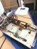
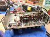
21AB95B8-75BE-4125-9D73-82849207A548.jpeg
7BFA5C27-4090-4701-80E6-0537B78BA1D8.jpeg
EAC86E63-8CC9-411E-BE3B-DD730DE32681.jpeg
726FDE8A-0873-4C91-8120-2E87E88E08EC.jpeg
 
Register to hide this ad
No doubt the problem will be found somewhere within this list:

1. Caps at C10 and C11 are leaking. Bumble Bee caps are famous for it.

2. R21 and/or R23 are off spec.

3. R30, C13, or the Rect are bad or out of spec.

4. The wrong tube is installed in the 12AX7 driver position.

Good luck with it!

Dave
 
Thanks very much to you both for these replies! Exactly what I was looking for. I'll go through and check all the possibilities you suggest and report back with my findings.

Interestingly - and I had forgotten about this - when I first got the problem amp, it did indeed have the v2 position 12au7 in the v1 (12ax7) spot, and vice versa.

I corrected this error when I swapped out all of the original small signal tubes, but as I mentioned the red plating has persisted.

I wonder how long it had been like set up or run like this by the seller and whether such a mistake could have caused any of the possible faults you suggest above?

Thanks again - very helpful!
 
I'd probably blame C10 and C11 caps first honestly. That type of capacitor is terribly unreliable after a half century or so. If you have a cap tester that can run them at high voltage, that will ring it out very quickly. Failing that, simply pulling one end loose from the circuit will do it too. It won't pass signal but if the cap is leaky it will stop it from red plating.
 
Spend some time in the archives over at the Mac forum here at AK. Approaches to MC30 has been extensively discussed. There are also tid bits in the Hints and Kinks stickey over there too.

Frankly, if the amp are all-original underneath, here's your strategy to get them back to a reliable set of amps in priority order:

- Rebuild the power supply - caps gotta go. Check the big resistors to be in spec but suspect them anyway.

- Rebuild the Bias Voltage circuit. See the Hints and Kinks stickey for how to change the resistors to accommodate a new silicon diode.

- All coupling caps are next. As you're seeing, they're already leaking. There's no way to fix that except to swap them out.

- Lastly, as discussed extensively, those old carbon comp resistors will tend to crack after the board flexing you'll be doing to swap the caps in the step above. There's likely ones in there that have already drifted and more will do so once you get the amps running. The heat-up/cool-down cycles can cause more of them to drift. The operating voltages called for are the best to way to find them. Or, you can do like some have suggested and 'blue print' the whole board with new resistors and be done with it. That's your call.

Cheers,

David
 
Spend some time in the archives over at the Mac forum here at AK. Approaches to MC30 has been extensively discussed. There are also tid bits in the Hints and Kinks stickey over there too.

Frankly, if the amp are all-original underneath, here's your strategy to get them back to a reliable set of amps in priority order:

- Rebuild the power supply - caps gotta go. Check the big resistors to be in spec but suspect them anyway.

- Rebuild the Bias Voltage circuit. See the Hints and Kinks stickey for how to change the resistors to accommodate a new silicon diode.

- All coupling caps are next. As you're seeing, they're already leaking. There's no way to fix that except to swap them out.

- Lastly, as discussed extensively, those old carbon comp resistors will tend to crack after the board flexing you'll be doing to swap the caps in the step above. There's likely ones in there that have already drifted and more will do so once you get the amps running. The heat-up/cool-down cycles can cause more of them to drift. The operating voltages called for are the best to way to find them. Or, you can do like some have suggested and 'blue print' the whole board with new resistors and be done with it. That's your call.

Cheers,

David

I posted a very similar summary on the Mac Forum at virtually the same time.
 
Thanks so much everyone. I should have the parts I need to rebuild the power supply and bias supply by Monday. As advised, I'll knock those out first.

I've touched base with Jim McShane and he has what look to be nicely assembled kits for the remaining resistors/caps. I'll likely pull the trigger on that next week and get both of the amps done at once.

Really looking forward to hearing how these sound once properly sorted.

Really appreciate the guidance here and I'll report back on my progress. I'll also delete the Mac forum post to keep the conversation focused here.

Thanks again!
 
+1 on the Jim McShane kits. Andy (NJPhenoix) rebuilt my MC40's with kits from Jim and they are the cornerstone of my system. I couldn't imagine trying to guess what caps to use in the different circuits, Jim has vast experience rebuilding amps and puts together a very nice package. Money well spent.

BillWojo
 
Jim is my go-to guy for tubes. He's done a good job over the years taking the mystery out of component selection for Citation and Mac tube gear. While I can make those types of decisions, I still check with Jim who has been most forthcoming with excellent logic and analysis to back up his suggestions.

Cheers,

David
 
Quick update - I've replaced the power supply cans with Authenticaps and received parts for the rest of the rebuild from Jim McShane yesterday.

Jim has been absolutely fantastic to work with.

I'll keep you all updated as work processed and try to get some pics up as well.
 
Jim's bypass caps for the PS & bias make a substantial impact on the overall performance of these amps.
 
Hey folks - so here's where I'm at: I've finished installing all the parts from Jim McShane's rebuild kits.

All the original caps have been replaced with Jim's mix of Russian KY40 PIOs and Panasonic (and a couple Nichicon) polypropylene film caps. I went with Jim's electrolytics and Authenticaps in the power/bias section and have Jim's bypass caps installed there as well.

I'd estimate fewer than 25 percent of the original caps tested close to spec and many were way off.

So caps and power supplies are done!

I've installed all the resistors Jim includes, which are primarily Dale/Vishay metal films, and a few of my own - Kiwame 2 watt 1% carbon films for the 1% matched R19 and R20 at 12k, and Takman REX 1 watt 1% carbon films for R22 (R22s because I broke one of the originals at one point).

Based on info from Jeff Day's blog, I also decided to spring for NOS 5 watt Allen Bradley carbon comps for the R5 and R13 spots, which *just barely* tested within 10% of spec.

The resistors I've tested have been as bad as the old caps - few within spec.

I was hoping not to have to take dshoaf's advice to just blueprint the amps, but I think this is the way to go. No sense in putting in this much time/effort and leaving bad resistors in place.

So since I have them open and on the bench, I'm gonna be done with it and replace all the remaining original resistors - about half the total are left.

So my question to you learned gentlemen is, what resistors should I use?

Carbon film or metal film?

Any specific models you all like (or dislike) from experience?

Schematic calls for .5 watt resistors for most of what's left to replace. Should I go to 1 watt for the remainder, or ok to stick with .5 watt?

Finally - do any particular resistor positions warrant a specific selection? (some have mention grid stoppers as needing something specific).

I appreciate any and all advice. I'm after what sounds best vs what's cheapest and at the moment am leaning toward (Takman?) carbon films based on what I've read. But really, I've no idea what I'm doing here.

Thanks in advance fellow AKers!
 
Last edited:
I used metal films. Carbon films are completely fine as well. 1/2 watt where spec'd. You're going to love the sound of those amps when you're done. I used K40y PIOS and the Panasonic films w/Jim's bypass caps. The amps are so fluid and dynamic.
 
I used metal films. Carbon films are completely fine as well. 1/2 watt where spec'd. You're going to love the sound of those amps when you're done. I used K40y PIOS and the Panasonic films w/Jim's bypass caps. The amps are so fluid and dynamic.

Thanks for this info! I'm curious - can I use 2 watt resistors in place of 1/2 watts, or is it specifically inadvisable?

Asking because I can get quite a few of the resistors I need as 2 watt KOA Speer carbon films, which I understand are rebranded Kiwames, from Mouser for about half the price of the Kiwames.
 
The rating, not so much. Their physical size is what will be the issue. They will be (too) large for some positions on that board.
 
Got it - thanks! I’m curious - since it’s just you and me talkin here - what, if anything, did you do with the power cord section on your mc30s?

I guess it doesn’t matter since the original wall plugs on these amps aren’t polarized, but one of my amps has the yellow power cord section coming in to the fuse, while in the other the yellow leg comes in to the yellow/black 117v PT primary tap. In both amps, the black PT primary connects on the fused side, the yellow/black on the non-fused side.

It really offends the OCD audiophile in me, but does it really matter? And can it be improved?

I’ve heard that hum problems can be introduced when folks have tried moving to a three prong type cord/grounding scheme. I’ve also seen people suggest it might be a good idea to sub a polarized two prong wall plug. Honestly, as long as it’s safe and I’m not leaving a performance improvement on the table I’m fine with it as is.

Other thing I’m curious about is Jim McShane includes a .01uf 1600v capacitor to be installed at the AC line in, just after the fuse where the black PT primary is joined (presumably neutral, but no telling which way the non-polarized AC cord is plugged in).

I can’t find a lot of precedent for this mod among MC30 owners and wondering if anyone has done it or might be familiar with its implementation in the mc30 specifically.

Is it more to filter noise and/or improve transformer isolation (my conclusion)? Or to improve the grounding scheme somehow?

Yes, I should just ask Jim - and I will tomorrow. I try to space out my stupid questions for him as much as possible.
 
There's a lot of discussion about using polarized and/or grounded plugs on older gear. I tend to use polarized plugs when I rebuild so that I know which leg is hot/fused. If i stick with non-polarized, I sometimes mark the hot leg on the plug with a dot of red paint. I have not had any ground loop problems.

That .01 1600v cap is meant to reduce ac line noise. I didn't put one in any of mine.
 
If i stick with non-polarized, I sometimes mark the hot leg on the plug with a dot of red paint. I have not had any ground loop problems.

That .01 1600v cap is meant to reduce ac line noise. I didn't put one in any of mine.

That's what I figured re: the cap. So I'm clear: in the MC30s, the fused side is neutral, correct?
 
Back
Top Bottom