

You are using an out of date browser. It may not display this or other websites correctly.
You should upgrade or use an alternative browser.
You should upgrade or use an alternative browser.
Help on McIntosh MC30 rebuild
- Thread starter jaaronb
- Start date
-
- Tags
- mc30 mc30 rebuild mcintosh


I fuse the hot leg. That way if a fuse blows there's no current running through the amp waiting for me to make a connection with my body.

jaaronb
Active Member
No, fused side hot.
I fuse the hot leg.
Good to know! In that case, should the hot/fused line pick up the 117v yellow/black PT primary lead, and the neutral/not fused line pick up the black PT primary lead? Vice versa? Or does it not matter?
Asking because both of my amps came wired with the black PT primary lead on the fused side.
Thanks for bearing with me here....
Your amps are wired correctly. Post some pics of your amps. We love porn here.
jaaronb
Active Member
Started to measure resistances this afternoon. Not exactly sure which voltage/resistance chart I should be using. My circuit layouts appear to be the same and so far have matched the standard ‘above 15,xxx’ schematics I’ve been using, but I seem to be getting a stray resistance reading or two that don’t align with the service manuals I’ve seen and are consistent across both amps (e.g, 12au7 - pin 7 to ground - 3.2M).
I’m gonna remeasure both amps to be sure I didn’t screw something up. Otherwise, cold resistances of both amps are ~ in the ballpark with the voltage/resistance chart I’m using.
Hopefully I can get the rest of the resistors replaces this week.
Until then, pics!
Don’t hold back - surely I’ve screwed something up here.
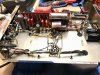
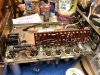
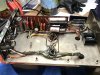
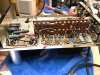
I’m gonna remeasure both amps to be sure I didn’t screw something up. Otherwise, cold resistances of both amps are ~ in the ballpark with the voltage/resistance chart I’m using.
Hopefully I can get the rest of the resistors replaces this week.
Until then, pics!
Don’t hold back - surely I’ve screwed something up here.
Looks good. Is that heat shrink around the K40's or tape?
Don't let those big solen bypass caps flop around untethered. I zip tied mine off onto a cable clamp attached to a tranny bolt.
Don't let those big solen bypass caps flop around untethered. I zip tied mine off onto a cable clamp attached to a tranny bolt.
jaaronb
Active Member
Thanks. That’s a 3M polyester film electrical insulating tape on the PIOs - any reason it won’t suffice? I need to trim the sides - I would have preferred shrink wrap, but didn’t have any clear on hand.
I used hot glue to affix the Solens, but I’d still like to attach them mechanically. I’ll try using the bolts and zip ties as well.
Planning to check and note the resistances tomorrow.
I used hot glue to affix the Solens, but I’d still like to attach them mechanically. I’ll try using the bolts and zip ties as well.
Planning to check and note the resistances tomorrow.
If it''s insulating tape, it should be fine. 
jaaronb
Active Member
Quick update - Measured and noted cold resistances in the amps today. From what I can tell, the circuit in both my amps matches the one here: http://www.timebanditaudio.com/mac.htm#mc30-4
Resistances are lining up from amp 1 to amp 2 fairly consistently and nearly all are are in the ballpark of Mac specs, except 1: pin 7 off the 12au7.
Spec calls for 2.5k. Amp 1 measures 3.03M, Amp 2 measures 3.26. It’s the only cold resistance spec where it appears both my amps are deviating from the schematic.
We’ll see what changes after I swap out the rest of the resistors. I’ll try tracing the circuit in the meantime.
Resistances are lining up from amp 1 to amp 2 fairly consistently and nearly all are are in the ballpark of Mac specs, except 1: pin 7 off the 12au7.
Spec calls for 2.5k. Amp 1 measures 3.03M, Amp 2 measures 3.26. It’s the only cold resistance spec where it appears both my amps are deviating from the schematic.
We’ll see what changes after I swap out the rest of the resistors. I’ll try tracing the circuit in the meantime.

arts
Addicted Member
Although McIntosh (and everybody else!) seemed to consider it acceptable practice back in the day,directly connecting high wattage resistors to an electrolytic cap is bad practice. Electrolytics don't like heat.While this did not seem to have a drastic effect on ''old school'' capacitors,the modern versions do not appear to be quite so forgiving.
I always make it a point to break the heat path by installing a separate terminal strip to isolate the hot resistor from the cap. Not a lot of effort or cost,just cheap insurance
I always make it a point to break the heat path by installing a separate terminal strip to isolate the hot resistor from the cap. Not a lot of effort or cost,just cheap insurance
jaaronb
Active Member
Just to confirm, are you grounding pin 2 of the 5U4GB when measuring this ? The manual says that one requires the jumper for measurement. Without it, I'd expect somewhere about 780K to ground.
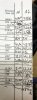
Sorry - I knew I shoulda mentioned that above...yes I am measuring the 12au7 pin 7 with the 5U4GB pin 2 jumpered to ground. What's more, all the other measurements (denoted by an '*') requiring that 5U4GB pin 2 to ground come out in the right ballpark....
I'm gonna put my measurements in a spreadsheet, but throwing this pic up in the meantime to illustrate.
Apologies in advance for my atrocious penmanship. 12au7 measurements are the middle set.
EDIT: Added a legible spreadsheet with all cold resistance measurements.
Attachments
Last edited:

must have an open resistor or connection somewhere around the 12au7 if its reading that high. How both would end up the same is very strange but the schematic says it should be a lot closer to the 2.5K they call for vs the 3M you're seeing.
unless the schematic is not accurate.
unless the schematic is not accurate.
jaaronb
Active Member
must have an open resistor or connection somewhere around the 12au7 if its reading that high. How both would end up the same is very strange but the schematic says it should be a lot closer to the 2.5K they call for vs the 3M you're seeing.
unless the schematic is not accurate.
Roger that. I'll check that area and remeasure after I've replaced all the resistors. Unless it's a deviation from the schematic, I'm guessing I screwed up in the same way on both amps.
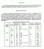
However, there is a later schematic, using the 152D labeled transformer and having the two additional c14 and c15 caps, which calls for 26M off the 12au7 pin 7. I'll compare the two to see what circuit change(s) might account for the difference. Source is here:
http://www.4tubes.com/SCHEMATICS/BY-BRAND/McIntosh/?C=S;O=A
Attachments
Hm, you know, maybe it is a manual error. The Sams shows a 2.2M resistor between pin 7 and pin 2 of the 12AU7. That would mean any resistance value has to be at least 2.2M, and it goes through some other stuff along the way. 3M is pretty reasonable given that.
for some reason I could have sworn that it gave 2.2K for that resistor. The official McIntosh schematic also does say 2.2M so I must have read it wrong.
http://www.vintagevacuumaudio.com/s...osh/mcintosh-mc30-owner-manual-schematics.pdf
R31 on the Mc schematic, R16 on the Sams.
for some reason I could have sworn that it gave 2.2K for that resistor. The official McIntosh schematic also does say 2.2M so I must have read it wrong.
http://www.vintagevacuumaudio.com/s...osh/mcintosh-mc30-owner-manual-schematics.pdf
R31 on the Mc schematic, R16 on the Sams.
I believe you have an interim build, just prior to the 3-14-60 schematic version with the 152D tranny.
jaaronb
Active Member
Makes sense to me. FWIW, the only circuit variation between my two amps I’ve found is at R17. Amp 2 (20557) has the 1.2K resistor called for by the ‘after 15,xxx’ schematic, while amp 1 (19470) had a 1.5k (may have been 1.8k - don’t remember) at R17.
These were differently banded resistors, not values that had drifted.
All else has been identical between the two.
I was actually expecting there to be more variation between the two given their 1000+ unit manufacturing separation.
Potential further evidence for my amps having an interim build is that some of the resistance values I measured were closer to the specs called for in the later schematic, rather than to the earlier one. These were specs that changed only slightly from one schematic to the other. We’ll see if that holds once I get all resistors swapped out.
These were differently banded resistors, not values that had drifted.
All else has been identical between the two.
I was actually expecting there to be more variation between the two given their 1000+ unit manufacturing separation.
Potential further evidence for my amps having an interim build is that some of the resistance values I measured were closer to the specs called for in the later schematic, rather than to the earlier one. These were specs that changed only slightly from one schematic to the other. We’ll see if that holds once I get all resistors swapped out.