• The move to the new server is done. There are some software and database maintenance updates in process. This has us passing the hat around to help out. We appreciate any donations. Seriously, even a dollar helps. The payment page may be found here - https://www.audiokarma.org/support.html

Help on McIntosh MC30 rebuild

i posted this in the Mac forum, but crickets over there so far, so thought I’d post it here. I can delete the original if there’s an issue with duplicates.

I picked up a couple of MC30s from separate sellers over the past week and can’t wait to get them up and running.

They’re as close in serial # as I was able to get given my complete lack of patience - 19470 and 20477 - both using the 150/152b trannies.

First order of business will be rebuilding the power supply and bias sections. The kits that Yves of Vintage Vacuum Audio sells for these first steps should be arriving today. (I was impressed with how responsive, helpful and nice Yves was during our quick exchange).

Both of the amps power up and make sound, as their sellers assured me they would. They sound great, in fact, but I only played them for a minute or so to look for immediate issues.

Tube complement for each is RCA 6L6GCs, original 5U4GBs, and a mix of small tubes from my own stash I know to be good - Raytheon (Baldwin) 12AX7, Sylvania Gold Pin 12AU7, and RCA (Hammond) 12BH7A.

So far, I’ve cleaned them up cosmetically and deoxed the tube sockets.

Amp #2 (20477) has no issues so far - I believe it had a cursory going over before I acquired it. The voltages I’ve measured so (not all) far are spot on.

Amp #1 (19470) has an issue. It wants to begin to red plate the output tubes within 5 minutes of startup. A cursory measurement of voltages on the output tubes gives me this:

V5
407 vdc - plate
410 vdc - screen grid
-35 vdc bias - control grid

V6
414vdc - plate
411vdc - screen grid
-37 vdc bias - control grid

I did change the tubes out on the #2 amp and the issue remains.

Plates are not bright red, but definitely getting some color on the bottom half of the plates after a few minutes.

The tube sockets in #2 did seem loose - the rectifier in particular. I have tightened the rectifier sockets a bit with a tiny flat head screw driver. It holds a little better when you pull with force, but can still easily be moved side to side.

Measurements were taken after I tightened the rectifier sockets.

I understand the red plating can be caused by poor contact of one of the 12ax7s (among other things), but I have no idea what implement to use to tighten the small tube sockets. I could barely get into the rectifier sockets with a tiny jewelers flathead.

My questions are:

Given those measurements, any guesses what the culprit might be?

What are the most crucial next voltages for me to measure - or should I wait until I’ve gone through the power supply and bias sections before taking additional measurements?

Anyone have tips on how to go about tightening the small sockets?

Finally, I’ll be rebuilding the power supply and bias in the next few days - are those changes likely to impact the issue I’m having?

If not, which other caps/resistors should I be looking at as possible failure points?

Thanks in advance for any and all assistance, tips, encouragement you folks care to provide. I’ve already gathered a ton of great information here.

View attachment 1024091
View attachment 1024094
View attachment 1024095
View attachment 1024096


You may want to replace that celinium rectifier. If your bias voltage is that high, could be part of your problem. To get you in the ball park stick in a 1N4007 and meas the bias voltage. If its too low (too negative a number), you can always bring it up with a resistor change.

best
 
If I may -- the effort to make the voltages match to a very tight level between the two units is certainly a laudable goal, but much more applicable in the practical sense to zero feedback SET type designs where there is no corrective capability to account for minor differences between otherwise identically built mono channels. With the Mac design however, there is such corrective action built into the design, that (imo) one would be very hard pressed indeed to tell the audible difference between two MC-30s that have voltage levels even 10% or more off from each other. Still, I know full well the satisfaction of making two channels perform and act identically electronically. Over the years however, I have come to realize that the chase for such perfection is more of a personal satisfaction, than producing any audible difference I could detect.

Regarding the output stage bias, like so many Fisher, Scott, and other manufacturers who did not provide any means to adjust the fixed bias operating parameters of their units, Mac did not provide any such controls either, except that in the case of Mac, none was really needed -- then or now. In the case of the other manufacturers however, they certainly are needed now.

Fisher and Scott used conventional output stage designs that run the output tubes high up in Class AB operation (as high a they practically could) to satisfy a number of design economies. By not providing any means to adjust the bias then, it meant that for proper and dependable operation, you really needed to obtain replacement tubes from the manufacturer, since only they knew what the required characteristic of the specified output tube was to achieve the correct quiescent current for the level they had set the fixed bias voltage at in the design. With these types of designs, operating the tubes at the correct quiescent current is everything for proper performance, and good tube life. There is little room for deviation as even moderate movement to operate the tubes cooler or hotter, and distortion rises quickly, or the tubes burn up respectively. With the manufacturers of these units long gone then, and the wide characteristics that manufacturing tolerances can produce in vacuum tubes, adding adjustable bias controls or altering the value of fixed value components to achieve the proper operating point is very important, and has been a weekend project for many a vintage audio enthusiast.

With the Mac design however, things are quite different. The output tubes are run very low in Class AB operation, as the beauty of the Unity Coupled output stage affords that ability. While the quiescent current of an output stage will always have an effect of the performance it produces (even with Mac), in the case of Mac, the effect is quite small -- to the point that distinguishing between even a significant difference in quiescent current would be a tall order. Now Mac in fact screened its tubes just like Fisher, Scott, and others did. But in their case, other things like ensuring the presence of adequate heater/cathode insulation was just as important as ensuring a general operating point characteristic, if not more. In a Mac Unity Coupled design, as long as the output tubes are reasonably matched, the circuit is quite insensitive to the actual operating point they operate at. Still, I am very aware of having everything just right in our prized equipment.

I know that prevailing wisdom for Mac equipment is to use a variac and adjust the bias voltage so it is exactly that of the schematic value when the B+ is at the schematic value as well. But this approach completely removes the characteristic of the tubes actually installed from the equation, and rather relies on the bias voltage to be set to a bogey value established by Mac. But in the quest for idealism, the bogey value for bias is only ideal if tubes of Mac's bogey characteristic are installed. Such would rarely be the case today with modern manufactured tubes, or even NOS NIB tubes that were not filtered through Mac's testing criteria. Therefore, a much better approach would be to adjust the bias for the bogey current that Mac intended the tubes to operate at, which then causes the individual characteristics of the tubes installed to fall out of the equation. This can be easily done by lifting the CT ground connection of the OPT cathode winding, and temporarily installing a precision 10Ω resistor between that lead and ground. Now the bias supply can be adjusted to whatever bias voltage produces the intended target current draw for the two tubes. Mac typically operated its 6L6 based designs employing rectifier tubes at about 50-55 mA of quiescent current per tube, but dropped this to about 45 mA per tube in designs with SS supplies. Once the bias is set, remove the resistor and reconnect the lead to ground.

Dave
 
That's what I thought. Just ordered a pair of late 50s tall bottle RCA 5U4GB. RCA 12bh7a also.

Is anyone familiar with the use of earlier ST-style 5U4Gs in these amps?

Different voltage drop & current spec. See below.


Tube# - Base - Fvolt - Famp - Vdrop - MaxPmA - MaxPv - notes
5U4-G - 5T - 5.0 - 3.0 - 44 - 225 - 450 - octal 5Z3
5U4-GA - 5T - 5.0 - 3.0 - 44 - 250 - 450
5U4-GB - 5T - 5.0 - 3.0 - 50 - 275 - 450
 
Therefore, a much better approach would be to adjust the bias for the bogey current that Mac intended the tubes to operate at, which then causes the individual characteristics of the tubes installed to fall out of the equation. This can be easily done by lifting the CT ground connection of the OPT cathode winding, and temporarily installing a precision 10Ω resistor between that lead and ground. Now the bias supply can be adjusted to whatever bias voltage produces the intended target current draw for the two tubes. Mac typically operated its 6L6 based designs employing rectifier tubes at about 50-55 mA of quiescent current per tube, but dropped this to about 45 mA per tube in designs with SS supplies. Once the bias is set, remove the resistor and reconnect the lead to ground.
 
Therefore, a much better approach would be to adjust the bias for the bogey current that Mac intended the tubes to operate at, which then causes the individual characteristics of the tubes installed to fall out of the equation. This can be easily done by lifting the CT ground connection of the OPT cathode winding, and temporarily installing a precision 10Ω resistor between that lead and ground. Now the bias supply can be adjusted to whatever bias voltage produces the intended target current draw for the two tubes. Mac typically operated its 6L6 based designs employing rectifier tubes at about 50-55 mA of quiescent current per tube, but dropped this to about 45 mA per tube in designs with SS supplies. Once the bias is set, remove the resistor and reconnect the lead to ground.

Thank you for providing this info Dave. FWIW, Jim McShane pointed out to me the same flaws in setting bias based on a fixed figure at target B+ for the same reasons you do, and also recommended using current draw to set the proper bias as you are here.

I get conceptually how this makes more sense, but despite your clear description, I still don't understand which OPT lead/where physically to tap to measure install the 10 ohm resistor to ground. Would this be, eg, on the secondary side of the OPT,

Does this method mean I'd be measuring current draw for each output tube separately, or both combined? Would I take measurements at idle?

Can I alternatively measure each output tube's current draw by dividing the DC voltage from pin 8 to ground by the DCR of the OPT cathode winding (OPT resistance measured with amps off)?

Sorry for the some questions, I'm clearly in one my head here. Your comments about the tolerances of these amps and understanding perfection may not be achieved (or necessary) with regard to measurements was encouraging!
 
Jaaron -- If you look at the schematic of your amplifier, there are four separate windings that make up the total windings of the OPT: There is:

1. The load bearing secondary winding. This is the winding that offers the various output taps that you connect a speaker or sound distribution system to. This winding is not the one I am referring to, and is grounded by way of a jumper on the speaker terminal block between the Ground and Common terminals.

2. The tertiary feedback winding. This winding has one side of it directly grounded, while the other side provides global negative feedback around the amplifier via R13 and C7. This also is not the winding I'm referring to.

3. The traditional primary winding that connects to the plates of the output tubes and B+. This also is not the winding I'm referring to.

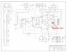
4. The cathode feedback winding. On the schematic, this is shown as drawn between pin 8 of each output tube, and is the winding I'm referring to. While it appears to be a separate coil on the schematic, it is in fact a separate coil within the OPT, that is wound very tightly with the traditional primary winding of #3 above. You will note that the center of this coil has a tap that is connected directly to ground. This is the lead that should be temporarily disconnected from ground and have the resistor inserted between this lead and ground. The lead is typically black in color. If you disconnect the black lead the OPT from ground, and there is then no longer any continuity between pin #8 of either output tube and ground, then you have disconnected the correct wire to insert the resistor in. If you still get continuity, then you have not disconnected the correct lead.

The readings across the resistor indicates the current draw for BOTH output tubes, with the reading taken under quiescent (no signal) conditions.

On the other hand, it is certainly possible to use the resistance of the winding from terminal #8 of each output to ground, to establish what the quiescent output tube current flow really is. You will want to use the resistance reading that is specific to pin #8 of each output tube, and you will want to take the readings -- both for the resistance, and the resulting voltage produced -- under the same thermal conditions; this to eliminate the effects of heating on the copper wire used to wind the windings within the transformer. Therefore, take/make the readings with the transformer either at room temperature, or at stabilized operating temperature, although room temp readings would be the most practical to use. In this case, the current draw computed at each individual output tube terminal #8 represents the current draw for THAT particular tube. The voltage reading at terminal #8 of any output tube is taken under quiescent conditions.

Dave
 
Thanks very much to you both this. I can't tell you how helpful the AK community has been. Funny that I thought blueprinting the amps would be the hard part. I'm travelling on business and was having a hard time ID'ing the right OPT lead with just the schematics I have on me.

I'm very curious to see if the amp that was running warmer is drawing more current, despite the B+, finals plate voltage and bias voltage being within a percent or two of one another. I'll report back as soon as possible when I return home Friday.

Based on the above guidance from @dcgillespie I understand I'll be looking for a target of 100-110mA of current using the resistor method (50-55mA per tube). Is this correct?

Thanks again gentlemen...looking forward to reporting my findings.
 
Hey folks - quick update. I installed a fresh quad of output tubes and took new voltage measurements. I've attached a did here with all the voltage measurements.

I wound up having to go up to a 10.3k dropping resistor on each of the amps to achieve a ballpark bias at 440v on the output tube plates, *as well as* acceptable current draw from the output tubes.

Here are the major voltages. Only odd thing to me is that I needed to put about 131vac on the amps from the variac (yes, I measured vac out) to achieve 440v on the plates. This does correlate to my original measurements off the 117v taps, when my mains ac voltage of ~122.5v gave me 440v on the plates.

Anyhow:

@131vac:

Amp 1
B+: 460
Plate voltage: 440vdc
Bias: --42.6
Cathode to ground v5: .806
Cathode to ground v6: .101
Fil voltage: 6.7vav

Amp 2
B+: 460
Plate voltage: 440vdc
Bias: -45
Cathode to ground v5: .816
Cathode to ground v6: .898
Fil voltage: 6.7vac


Voltages at typical mains VAC of 122.6:

Amp 1

B+: 430vdc

V5/V6 plates: 410vdc

V5 bias: -40.2vdc

V6 bias: -40.07vdv

V5 cathode to ground: .730vdc

V6 cathode to ground: .895vdc


Amp 2

B+: 432vdc

V5/V6 plates: 410.6vdc

V5 bias: -41.6vdc

V6 bias: -41.6vdc

V5 cathode to ground: .735vdc

V6 cathode to ground: .826vdc


OUTPUT TUBE CURRENT DRAW:

OPT cathode winding resistance - both amps identical:

OPT cathode winding resistance V5: 13.2ohm

OPT cathode winding resistance V6: 15.8ohm


Amp 1 output tube current draw:

V5: .730vdc/13.2ohm = 55.30ma

V6: .895vdc/15.8ohm = 56.64ma


Amp 2 output tube current draw:

V5:.735vdc/13.2ohm = 55.68ma

V6: .826vdc/15.8ohm = 52.27ma


@dcgillespie or others - how is this looking? Did I measure output tube current correctly here? I've been running the amps for a couple of days to let them settle and am going to remeasure over the weekend.

Obviously, I'd need to go a resistor value or even two higher (particularly on amp 2) to get these amps to bias at the spec'd -42vdc when 440 is on the plates of the output tubes. But that would give me significantly more current draw also.

Even though 95% of my voltages match spec (see the 12au7 values in the attachment, which are off) , it seems like amp 2 wants to be biased closer to -45.

If the above values hold after a week or so, am I good to call it done? What do you all think?
 

Attachments

Last edited:
As I said before B+ isn t a critical # here.
I suspect your amp, if checked on a bench would meet spec.
Bumping up the ac in to achieve the B+ is making your filament v high.
Your tubes will have a significantly shorter life span at 6.7.
I'm curious at normal line in v , where do the #s come out. I bet that's a better real world operating point
 
The one and only voltage that is a "constant" to ideally achieve is 6.3 VAC across the heater bus. After that, the bias supply should be ca center of spec range. Whatever the other voltages are with all proper component values established and with a known good set of tubes is what they are, full stop.
 
Agreed on the heater voltage. Get it to within -0/+4% at the heater terminals on the tube socket that is electrically farthest from the power transformer heater winding leads. The B+ voltage will be what the B+ voltage will be. With the heaters operating at the correct voltage, then adjust the output tube bias voltage so that the output tube current draw is in the 50-55 mA range. The bias voltage will be what the bias voltage will be, and be largely dependent on the particular output tubes installed. If the heater voltage and output tube current draw are on target, that is by far and away the most important points to zero in on. Where everything else settles in will be just fine.

Dave
 
The one and only voltage that is a "constant" to ideally achieve is 6.3 VAC across the heater bus. After that, the bias supply should be ca center of spec range. Whatever the other voltages are with all proper component values established and with a known good set of tubes is what they are, full stop.

I've consistently gotten 6.7vac across the heater bus with my normal ac mains voltage of ~122.5vac, using the 125v primary tap. On the 117v tap, I got 7.1vac on the heaters.

I need to get a thermistor, don't I?

EDIT: or is there another way to lower the heater voltage?

Which thermistor do I need again?
 
...to be clear, I've consistently gotten the same filament voltages of 6.69-6.7vac on all tubes in both amps, regardless of fluctuations in my normal mains ac, dropping resistor changes in the bias section and tube changes.

Filament voltage readings off the variac at 131vac were ~7.15vac vac in both amps.

Filament voltages were similarly fixed in both amps at ~7.1vac off the 117v tap using mains ac.

FWIW, I've read a few accounts from others who could/did not get below 6.7vac filament voltage off stock MC30 builds in models close to my serial numbers of 19xxx-20xxx.
 
Last edited:
The one and only voltage that is a "constant" to ideally achieve is 6.3 VAC across the heater bus. After that, the bias supply should be ca center of spec range. Whatever the other voltages are with all proper component values established and with a known good set of tubes is what they are, full stop.

Quick question: I note that the schematic calls for 6.3vac across the heater bus at *30 watts out*but gives no spec'd AC voltage at idle/no signal.

All of my measurements have been taken at idle/no signal. I

s there a chance my heater voltages would come down at the spec'd 30 watts output load?

If so, how would I go about achieving/measuring it?

I could use a simple sine wave generator for input signal, but not sure how to achieve/measure 30 watts out.

Here's the schematic page for reference: http://4.bp.blogspot.com/-1l4tIE-9ATY/UxYaIzfZRxI/AAAAAAAAAPs/Re2d-qmukhk/s1600/man2.jpg

Thanks for bearing with me on this....
 
While it looks like the spec is given under a condition of 30 watts output, that is not the intended interpretation. The intended understanding is that pin #2 is a filament terminals, and should measure 6.3 vac to terminal #7. The information supplied in the horizontal columns for these two terminals has no bearing on the titles given to the vertical columns. The point is that these terminals are the filament terminals, and that the voltage between them should measure 6.3 vac under any of the operating conditions noted.

Use a Current limiter that is appropriate for the fuse size of the unit. A 2A - 2.5A fuse would use a CL-90, while a 3A (or there abouts) would use a CL-80.

Dave
 
Agreed on the heater voltage. Get it to within -0/+4% at the heater terminals on the tube socket that is electrically farthest from the power transformer heater winding leads. The B+ voltage will be what the B+ voltage will be. With the heaters operating at the correct voltage, then adjust the output tube bias voltage so that the output tube current draw is in the 50-55 mA range. The bias voltage will be what the bias voltage will be, and be largely dependent on the particular output tubes installed. If the heater voltage and output tube current draw are on target, that is by far and away the most important points to zero in on. Where everything else settles in will be just fine.

Dave
This is really the last word on setting these amps, with known good tubes and all passive components in spec and working properly, meaning no drifted resistors or leaking blocking capacitors.
 
While it looks like the spec is given under a condition of 30 watts output, that is not the intended interpretation. The intended understanding is that pin #2 is a filament terminals, and should measure 6.3 vac to terminal #7. The information supplied in the horizontal columns for these two terminals has no bearing on the titles given to the vertical columns. The point is that these terminals are the filament terminals, and that the voltage between them should measure 6.3 vac under any of the operating conditions noted.

Use a Current limiter that is appropriate for the fuse size of the unit. A 2A - 2.5A fuse would use a CL-90, while a 3A (or there abouts) would use a CL-80.

Dave

This is really the last word on setting these amps, with known good tubes and all passive components in spec and working properly, meaning no drifted resistors or leaking blocking capacitors.

Thanks so much gentlemen - I sincerely appreciate your expertise and assistance with this. Ordering some CL-80s now.

I'm assuming one thermistor goes on each hot leg, but I'm ordering extras anyway.

I'll report back once I get them installed.

Care to hazard a guess as to how significant a drop I can expect to see on the heaters?

Is it safe to assume the high heater voltages don't indicate any broader problem with the amps...assuming all resistors and caps are in spec?

Thanks again!
 
Back
Top Bottom