• The move to the new server is done. There are some software and database maintenance updates in process. This has us passing the hat around to help out. We appreciate any donations. Seriously, even a dollar helps. The payment page may be found here - https://www.audiokarma.org/support.html

Help please. Sansui AU 719 kill left channel

To be honest with you, I don't think you will be able to learn on this one...
My advice to you is to find a tech that at least fix your unit. Which BTW would be a good candidate for reconditioning.

Hippocrates, I tried to send them to a well-known technician but from the start he was already selling me some transistors, he was not clear with the information, he reduced everything to transistors, he knows these devices so it seemed strange to me; The amplifier had transistors changed four years ago, the technician who did it is no longer available. At least thanks to you I have verified that the transistors are not the problem (if so, in no way would I get audio from the left channel). I want to see how far I can go, to be prepared and go to another technician and not get me caught in a poke.
 
Fair enough.

OP.
Before attempt to fix this.

Google this.
1. Safety when dealing with electronics.
2. What are diodes, transistors, resistors and capacitors.
3. What is DC?
4. What is AC?
5. How to measure resistance and voltages(AC/DC) with a digital multimeter.
6. How to test a Diode.
7. How to test a transistor with a DMM
8.Schematic symbols.

With that covered you will be able to recognize components and make measurements, to post some info in order to grispato (who knows this unit) assist you.
 
Fair enough.

OP.
Before attempt to fix this.

Google this.
1. Safety when dealing with electronics.
2. What are diodes, transistors, resistors and capacitors.
3. What is DC?
4. What is AC?
5. How to measure resistance and voltages(AC/DC) with a digital multimeter.
6. How to test a Diode.
7. How to test a transistor with a DMM
8.Schematic symbols.

With that covered you will be able to recognize components and make measurements, to post some info in order to grispato (who knows this unit) assist you.

I'm sorry, I haven't completely read everything you recommend, I'm going to go more calmly, trying my best, I haven't reviewed point four of your recommendation, today I will. And I will address these queries you suggest. Thanks!
 
You can learn on this one. I did.
But it will need some proper preparation. At least the little list Hipocrates gave before.
But I have to admit, if you can not find the powersupply, voltages and there related physical location/ pins. . .
I would almost ask : did you try?
Understand, you are only going to learn this by trying, not by someone telling you every step.
Just poking around without first and on the way learning is not going to bring results. Unless you are really lucky and you bump into the problem accidentally.

I understand, I don't believe in luck so the way is to read and try as much as you understand. What you have told me has been very helpful and even though I have not followed your instructions to the bottom, I am going to do the task without any hassle. Thanks!
 
I'm going to go more calmly, trying my best, I haven't reviewed point four of your recommendation, today I will. And I will address these queries you suggest. Thanks!
Just take your time to understand what are you doing. We're going to be here if you need it.
Grab an old radio or build some chip amps from ebay for practice and build some small dual linear power supplies, and you will learn a lot.( what components do, soldering/de-soldering)
 
I understand, I don't believe in luck so the way is to read and try as much as you understand. What you have told me has been very helpful and even though I have not followed your instructions to the bottom, I am going to do the task without any hassle. Thanks!
Good to hear you were not discouraged by my message!
I can understand it may have sound a little harsh, good you didn't take it that way.
It was meant as a reality check.
I can recommend the tutorial mentioned by hypocrites from Conrad's site.
Read it several times. It will give you insight in the process. Most important point he makes: "troubleshooting is done mostly with the mind, not with the soldering iron!"
My first amplifier that I repaired/ restored was an AU-719. I managed to do this with the help of some members of Audiokarma, but even more by reading a lot of threads on here about restoring, learning from books and other internet sites like Elliot sound.au what are the basics of a audio amplifier circuit, its powersupply and the components. This happened before I started but also during the process.

Here is the schematic of the control amplifier.

Screenshot_20220904-083906_Moon+ Reader.jpg
The top part with the transistors contains most switches and the volume potentiometer and the amplification circuit for when the tone control switch is on ( S3 ). When you look at S3 you can see that is drawn at both sides of the amplification circuit. The position numbered 1 is connected from both sides with a line. This means when the tone control switch is in 'off' position the amplification circuit is bypassed. This means that when you use the aux or tuner input terminals the signal only will go through some switches and potentiometers and it will not even depend on the regulated powersupply.

Then a picture of the powersupplies.
Physically this is located on the same board as the protection circuit. ( Remember, schematic is what it name implies, not a direct representation of the real world, but a schematic, so we can see the flow and identify components in that flow easily).
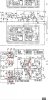
Screenshot_20220904-084708_Moon+ Reader.jpg

The part with Nr 1 is the regulated powersupply which provides power for the equiliser board and the tone control board.
The part with Nr2 is the powersupply for the driver boards and the output transistors. Realize that part of this is wired point to point ( the main filter capacitors) and part of it is on the board ( rectifiers, fuses).

Then the driver boards.
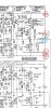
Screenshot_20220904-085536_Moon+ Reader.jpg
Screenshot_20220904-090508_Moon+ Reader.jpg
I circled the connections to/ from this board. Red are the powersupply / ground connections, blue the signal connections. The numbers you can find on the boards to, the letters are to find the connection to other boards/ locations in the schematic.
Download the service manual from Hifi engine or AK digital doc and study this. This way you can find them in your amplifier ( without power on).
When you start to feel comfortable with finding connections on the boards you can start measuring voltages. You can compare voltages between both channels. Don't go measuring without knowing what you will expect at that location, no use for that.
Be sure you understand what measuring voltage means and how to do it.
Good luck.

 
Last edited:
And beware of multimeter 'probe slips', it can be easy to short pins together when measuring, if you do this you can do a lot of damage - take care. ;)

The use of 'mini-grabber' multimeter leads (rather than standard 'probes') can help prevent this. You can also insulate all but the very tip of your multimeter probes with electrician's tape, this can help too.

Update:
Consider buying and using 'mini-grabbers' but attach them with the amplifier powered off. By so doing you eliminate a fumbled connection attempt with power applied, and can power on when you are sure your connections are safe. The same applies for disconnection, power off first then disconnect meter connections. ;)
 
Last edited:
And beware of multimeter 'probe slips', it can be easy to short pins together when measuring, if you do this you can do a lot of damage - take care. ;)

The use of 'mini-grabber' multimeter leads (rather than standard 'probes') can help prevent this. You can also insulate all but the very tip of your multimeter probes with electrician's tape, this can help too.
John, believe it or not i recently cooked freshly installed output transistors(originals failed) on my Accuphase. Accuphase has it's boards installed into connectors and then female part of the connectors has pins where wires attached. So I was going to measure idle current using mini-grabbers leads. Somehow probably by not paying attention and because of not adequate lighting i did not realize that i pushed to extend the grabber too much and way before reaching the pins. So result ruined my day. I basically shorted 2 pins killing OT and hard to find Sony TO-66 driver. Now probably for me the only option is TO-220 instead of TO-66. Sorry for being a bit off topic.
Was really upset with myself as it did not happen to me for a long time.
 
Last edited:
Was really upset with myself as it did not happen to me for a long time.
Oh dear, I am sorry for you, unfortunately it happens to the best of us, I did a similar thing with my AU-X1, but only destroyed a driver transistor thank goodness.

For the experienced among us this is a 'once in several years' event, if that, but for real Noobs it is almost guaranteed to happen. :(
 
Hello friends, I am currently checking the power supply board, I checked all the resistances of the supply (those that start with the letter R in the manual), I am using a basic multimeter; I found two inconsistencies R01 is 4.7 Kohm when I apply the meter it easily goes up to 1.4 kohm but from then on it charges very very slowly, I have the feeling that its companion R02 had this behavior but at this moment it is much faster than R01; I also found what seems to be an empty space TR605, where there should be a transistor, there is welding material there, reviewing photos on the internet of this board, I saw that a transistor goes in that space, inside the amplifier I did not find this transistor fallen, Probably the technician who repaired it removed it and did not replace it.
I'm looking forward to getting a basic LCR meter, if I can recommend one keep an eye out.
 

Attachments

  • IMG_0704.jpeg
    IMG_0704.jpeg
    122.8 KB · Views: 15
R01-04 are parallel to each of your filter capacitors. The reason for inconsistent readings, and I doubt your problem is with them.
Tr605 is one of the transistors that make your protection light blink. So although something weird there is will not be causing your problem.
 
@Mauricio719 - That's not TR605 that has been removed but the Thyristor SCR601 - possibly someone has removed to circumvent the amp going into Protection(?) or it is faulty and they could not find as replacement - you need to investigate further
 
Last edited:
I found two inconsistencies R01 is 4.7 Kohm when I apply the meter it easily goes up to 1.4 kohm but from then on it charges very very slowly,
Those are bleeding resistors, their function is to discharge the big capacitors.
Can you read schematics?
What you need to measure is voltages with the black probe on the chassis and the red one to the point you want to measure.
 
Those are bleeding resistors, their function is to discharge the big capacitors.
Can you read schematics?
What you need to measure is voltages with the black probe on the chassis and the red one to the point you want to measure.
Hello, I started with the resistors because it seemed easier, I have reviewed the schematic only at that point, some resistors appear in the schematic, others do not and others are a little different, I measure the resistances with the amplifier turned off, I have not yet entered to measure voltages because I am not sure of how to do it. Could you give me an example?
 
R01-04 are parallel to each of your filter capacitors. The reason for inconsistent readings, and I doubt your problem is with them.
Tr605 is one of the transistors that make your protection light blink. So although something weird there is will not be causing your problem.
Hello, the other resistances measured without difficulties, in addition to the ones I mentioned yesterday, the R603 resistance is the slowest of all, at first I thought that it did not exceed 200khom.
 
Could you give me an example?
https://learn.sparkfun.com/tutorials/how-to-use-a-multimeter/all
https://www.mojotone.com/blog/fif-basic-amplifier-voltage-test-points

In order to follow what grispato is asking you to do, you will need to learn to read schematics, I will leave to him to guide you on this.
I will, however advice you to grab an old radio to practice, instead of your unit and study the lists of subjects that I gave you previously on post #19. Those 719 present some challenges specially when missing parts or previous attempts to repair it
Good luck.
 
Hello, the other resistances measured without difficulties, in addition to the ones I mentioned yesterday, the R603 resistance is the slowest of all, at first I thought that it did not exceed 200khom.
I would not worry about that. If, when you measure the resistance of a resistor, the value increases this is most often caused by a capacitor in parallel in the circuit. If you want to know the exact value you will have to lift one leg.
Because AUD101 found that it is the SRC missing is would not worrie about the protection board for now ( this would have been done most probably because it was broken and the technician didn't have a replacement.)
 
That connections are for ground and signal from outputs to relais. So when you change them from left driver board to right driverboard you can not have change of output channel at speaker terminals.
But is looks like you have one driver board/ outputs not working.
( Although it is not ruled out you don't have problems on the tone board and or its powersupply).
This one was wrong analysis of my side. This proves that it is your left driver board F-2926 and/or its powersupply/connections.
When you switch out these connectors you mostly switch left and right channel output signal. This means that the output of the right driverboard will go to the left channel loudspeaker terminals and vice versa.
Best to do is take the F-2926 out ( just 4 screws and connectors) and check it visually. Component side with regards to resistor discolouration or right out burn marks ( especially close to the little heatsink) and glue invested components ( mostly around the bigger capacitors). On solderside look for cold solderjoints.
This is the first step in troubleshooting now we determined the most likely location. It has to be done thoroughly so you (and we) don't go chasing your (our) tail later on.
 
And of course the powersupply for the left driver board. DC voltage should be around 65 Volt positive and negative.
Between positive terminal of C701 and the little bar in between the two capacitors ( positive), from the bar to the negative terminal of C702 ( negative).
 
Back
Top Bottom