• The move to the new server is done. There are some software and database maintenance updates in process. This has us passing the hat around to help out. We appreciate any donations. Seriously, even a dollar helps. The payment page may be found here - https://www.audiokarma.org/support.html

HELP! Restoration Question Planar SR2100 Receiver like Marantz

Paul89

Member
Hello all,

Cannot upload pics due to "cannot upload file chooser" ?!

I was wondering if anyone has ever restored one of these and if you can share your experience with it as it seems like a different built construction. If you're unfamiliar with this receiver, there are some old threads that talk about it being very well made. It's made in Canada!

Thanks very much!
 
Register to hide this ad
Hello all,

Cannot upload pics due to "cannot upload file chooser" ?!

I was wondering if anyone has ever restored one of these and if you can share your experience with it as it seems like a different built construction. If you're unfamiliar with this receiver, there are some old threads that talk about it being very well made. It's made in Canada!

Thanks very much!

I have the service manuals.
I will scan them in - if I get lost my email is rboys@earthlink.net as I am new here.
 
Hello
I emailed it to you - see if you get it. I will scan a better copy later.
I used to work at Electrohome and later at a store that sold these. We also sold PSB speakers and I have a pair of Beta II.

These receivers fared quite well against Japanese products. It was all designed and made in Kitchener (except for the tuner board).
There is a small PCB attached to the tuner and this was because a certain London FM station had their transmitter deviation set very low in an attempt to provide the best possible sound quality - but there was not enough audio - people had to turn the volume up too high and they didn't like this - this board fixed that.

Electrohome at the time were the CDN distributor for Marantz - and I think Marantz wanted to go direct so Electrohome decided to make their own. This was at the height of the audiophile market. Electrohome made big console stereos for many years.

The guy at Electrohome - Bob Parker ? He was the person who guided this project successfully. He ended up at running a Japanese stereo import house in Canada. He did a wonderful job on this - it was in the late 1970s I saw him last.

I started mine up after sitting for 20 years and after a few minor repairs - it works great.

Bob Boys
 
Hello
I emailed it to you - see if you get it. I will scan a better copy later.
I used to work at Electrohome and later at a store that sold these. We also sold PSB speakers and I have a pair of Beta II.

These receivers fared quite well against Japanese products. It was all designed and made in Kitchener (except for the tuner board).
There is a small PCB attached to the tuner and this was because a certain London FM station had their transmitter deviation set very low in an attempt to provide the best possible sound quality - but there was not enough audio - people had to turn the volume up too high and they didn't like this - this board fixed that.

Electrohome at the time were the CDN distributor for Marantz - and I think Marantz wanted to go direct so Electrohome decided to make their own. This was at the height of the audiophile market. Electrohome made big console stereos for many years.

The guy at Electrohome - Bob Parker ? He was the person who guided this project successfully. He ended up at running a Japanese stereo import house in Canada. He did a wonderful job on this - it was in the late 1970s I saw him last.

I started mine up after sitting for 20 years and after a few minor repairs - it works great.

Bob Boys
Wow that's pretty cool! That must of been a nice job that enabled you to be fully immersed into it. Indeed it's great to have a Canadian made receiver of such high quality. Some of the resistors look like the bumblebee bee ones from early marantz unit. Also has sprague caps and Motorola transistors.

I'm planning on restoring it to former glory as one of the channels is out. A thin orange wire that's attached to a yellow thin wire came loose so its nice to have the schematics. However, the undercarriage seems a bit complex as to how to remove the boards off the unit.

I'll give it a go soon and see how it goes. Also, not sure if the lamps are easy to find these days.
 
OK
If you can't easily follow the schematic - if you tell me where the wires are and/or a photo I will see where it goes on my 2100.
You test the power amps easily by unplugging the U-nails in the PRE-out and MAIN in connectors and swap the channels with an RCA cable - if the sounds comes from the other channel - the power amps are OK.
I will write down common problems with this type of equipment.
Bob
 
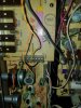
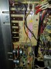
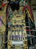
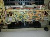
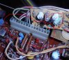
Here's pics of my unit. Please let me know what you think. Note the orange wire came loose.

The little small square board wires on the right seems to have bad solder joints?

Removing boards seems complex as some overlap
 

Attachments

  • 20211001_010851.jpg
    20211001_010851.jpg
    126.6 KB · Views: 49
  • 20211001_010838.jpg
    20211001_010838.jpg
    135 KB · Views: 45
  • 20211001_010956.jpg
    20211001_010956.jpg
    155.6 KB · Views: 46
  • 20211001_010924.jpg
    20211001_010924.jpg
    143 KB · Views: 43
  • 20211001_010911.jpg
    20211001_010911.jpg
    150.3 KB · Views: 44
  • 20211001_010904.jpg
    20211001_010904.jpg
    152.3 KB · Views: 44
  • 20211001_011024.jpg
    20211001_011024.jpg
    91.6 KB · Views: 40
  • 20211001_010711.jpg
    20211001_010711.jpg
    127.8 KB · Views: 43
  • 20211001_010746.jpg
    20211001_010746.jpg
    104 KB · Views: 46
I do not have those wires on my SR2100.

My resistors are 2.2K. These resistors are R540 and R640.
On my board it says (hand written) A06 and you have A04. Don't know what this means.
You have a real mystery here.

The audio you select with the SELECTOR SW501 switch go through these resistors via P513-5 and P315-6.
Then through all the TAPE selection and DUBBING switches and off to the volume and tone controls and then to the power amp.

Your wire appears to attach from the resistor and go to P516-5 which attaches to the Hi-Blend switch . This bypasses all the tape, volume and tone circuits..

I would expect this to cause the receiver to operate at full volume. Not sure why. I think I have it correct.
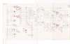
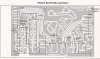
I attach some docs.
The small board looks OK.

What do you think ?
 

Attachments

  • schematic1.jpg
    schematic1.jpg
    71.9 KB · Views: 24
  • PushButton.jpg
    PushButton.jpg
    130.3 KB · Views: 18
Would it be wise to remove these wires (yellow and orange)? Or they are there for a reason.

For some reason, I'm more comfortable working on marantz units like I've done in the past but for some reason this seems to be different to me. However, I will tackle this on.

Do you suggest a starting to point as I want to recap it and I have most of the parts handy including resistors and transistors. Any notorious parts in this that are faulty after 40+years?

Thank for scanning the schems
 
Hi
I don't think you need those wires.

I think you should try and get it working before changing any parts. You could make a mistake or put in a defective part and now you have more problems to fix.

I can't imagine why the resistors would go bad ? Nearly all are Philips metal 5% very low noise and are high quality. Few are of old carbon - the resistors your wires are attached are carbon.
Frankly, I would not bother changing any unless burnt looking.

If you look closely at the transistors - you will notice many small signal start with a "B" number - these are from Europe and very special - low noise. Electrohome used to use a Siemens BC169C in their organs - and if someone replaced with a generic Japanese or US transistor - there was a lot more noise produced. Because of this - I wouldn't change any transistors unless you can get the originals. My guess is you will find the unit performs worse than now...transistors last a very long time.

I know electrolytics dry out - but once again - get it working perfectly before changing them....even then I wonder if it is worth it ?

Electrolytics need to be used to keep that dialectric film inside intact. In the old days (tube stuff) we used to "form" a new capacitor by turning it on and off a few times slowly to get it going. But then, the voltages then were 3 or 400 volts B+. I know Parker told me that they sometimes had a hard time sourcing Canadian made parts good enough (within cost limits) - he specified the best they could because he was competing against the best.

My 2100 is working after sitting here for 23 years doing nothing as well as my 1968 Ampex tube reel2reel, CD player, TV and a VCR and scope etc - I decide not to change all the caps until one breaks down. IMHO, changing all these parts diminishes the value - others for sure have different opinions. Besides, once you change all these parts - it doesn't look original anymore.

The connectors plugs are notorious for bad solder joints - as the years go by temperature changes break the solder up - there is not enough solder for the weight of the pins. On my 2100, the AM and FM didn't work because two of these pins solder connections were bad. The connectors themselves can use a bit of cleaning solution and moved to clean them.

The transistors sockets sometimes give trouble but not much. One of mine crackled - I sprayed some cleaner in it and inserted the transistor a few times and has been good since. Electrohome used these in TVs too to make servicing easier. A system is more reliable if soldered in.

Boards in most equipment are not meant to easily come out. Just part of the game I suppose.

Bob
 
Hi Bob,

I agree with you and I appreciate the information. I will not touch the resistors and transistors unless need be and its nice to know about them being special. Im a firm believer in if it ain't broke, dont fix it, however, as for the caps, I will change as much as I can just to have it up to specs (except for tuner board as I dont want to mess with the radio waves). I will not replace the filter sprague caps as I'd like to keep those original. Sprague is a top quality brand and I know thisbl because marantz uses them in their model 18 and 19. The resistors in the 2100 looks very similar to those found in the marantz model 18 and 19 which is quite surprising .

For the orange and yellow wires, I will wother keep or remove them depending on what's easier.

Can you please take pics of the items that go bad: plug connectors, transistors socket.

The board layout document failed to open on my end. Could you please email it to me? I know if yoire using an iphone it wont work for me as I'm using android. Is it a PDF?

Also can you take a pic of your 2100? What serial number is yours compared to mine? Have they made 7k plus units?
 
I was thinking last night that Electrohome in general was a big customer of Philips electrolytics - the experience there were very few failures. As they used Rubycon in Plannar they must have thought these were superior to Philips. A slight cost advantage would not make the difference to switch - it would have been quality. I think I will not change my electrolytics and see what happens. My stereo has very few hours on it. Changing them, especially for products made in early 2000s is a very good idea. https://en.wikipedia.org/wiki/Capacitor_plague My mother's 1969 RCA stereo surprisingly still works great. It is a big RCA console with guts made in Japan. She has some 78 RPM records. :-)

An old friend of mine worked on the two Voyager spacecraft about same time as Plannar - - he had worked on the design of the camera lens and color filters and gyroscope - I had asked him about any electrolytics in there (my girfriend got a new Apple motherboard because of this) and he didn't really know what was used - he was mostly optics. He did say the electronics technology was old (compared to today) and he is surprised the two of them are still working after all this time. I said maybe because it was such old technology... Old stuff can still perform.....especially in radiation of space.

I think you can remove the two wires. They do not belong there. Someone had a reason to bypass the tape switches and tone controls - maybe was part of a sound system in a business like a restaurant and had trouble people changing knobs ?? This is Is weird.
2100.JPG board.JPG
The capacitors with the colour bands are also Philips - metal film too - very low failure rate. It cost a ton of money to fix a piece of gear in the field so reliability was key but not always successfully adhered too. The tiny gum drop capacitors are tantalum and used only for low noise etc because expensive. I don't know if they dry out - some might. When defective they usually short. C632 and C532 on small board are tantalums. They can be self-healing after a short and I have seen this strange behaviour.

Marantz used Japanese resistors once they shifted production from the USA. They were also metal film. The resistors that would go bad were high value (megohm) and connected to high voltages like hundreds or thousands volts and found mostly in TVs. Regular carbon were better for this where noise and tolerance didn't matter. The look and feel inside your receiver is how Electrohome products looked like starting with the C10 colour TV. Even the schematics are the same. I attach a couple of boards from an organ. PCBs were mostly made by Lightning Circuits of Niagara on the Lake. Electrohome liked to make their products with lots of space on the boards to make servicing easier - compared to Japanese and some US stuff all smushed together and hard to get at. Electrohome like the recommendations of local repair people.

I uploaded a photo of the connectors and transistor socket - these are easy to spot. I tested the sockets by tapping very lightly with a pen to see if any noise came out - only one was dirty and easily fixed. Of course, a good idea to clean the pots and switches with some contact cleaner. My serial number is faded too hard to read. It is not a good idea to start your serial numbers at zero - your competitors can tell how many you are selling which is not good. I believe Electrohome numbers are sequential but don't start at zero. Not too sure though - that was a long time ago. At their peak - they made either 250 or 500 colour tv a day (I forget which). They were looking to double that but there were scaling problems especially from suppliers. I don't think they doubled production. The first digit is the product. I doubt Plannar production was very high. It was tough to sell anything CDN or American against the Japanese invasion such as Sony in this compact stereo market. Marketing is very complicated.

If you look on the top of the radio capacitor there are some big felt pads. These are there in case during shipping a mechanical resonance is set up and the PCB can get broken. I have seen this with other products too - they get destroyed during shipping. Really amazing......

The cardboard box these plannars came in was huge ! I don't think I have a picture - but it was very big. In those days big and heavy was good as it portrayed quality and value for the dollar.
organ1.JPG
organ2.JPG
 
I appreciate the history of this beauty. I haven't started her up in a while so I will plug it in again and see what the problem is exactly. The last time plugged in was a year ago and the guy I bought it from told me it wasnt working well and did a quick audition.

I will report back soon. I can now open the document you sent me in my email. Much appreciated
 
I was thinking last night that Electrohome in general was a big customer of Philips electrolytics - the experience there were very few failures. As they used Rubycon in Plannar they must have thought these were superior to Philips. A slight cost advantage would not make the difference to switch - it would have been quality. I think I will not change my electrolytics and see what happens. My stereo has very few hours on it. Changing them, especially for products made in early 2000s is a very good idea. https://en.wikipedia.org/wiki/Capacitor_plague My mother's 1969 RCA stereo surprisingly still works great. It is a big RCA console with guts made in Japan. She has some 78 RPM records. :)

An old friend of mine worked on the two Voyager spacecraft about same time as Plannar - - he had worked on the design of the camera lens and color filters and gyroscope - I had asked him about any electrolytics in there (my girfriend got a new Apple motherboard because of this) and he didn't really know what was used - he was mostly optics. He did say the electronics technology was old (compared to today) and he is surprised the two of them are still working after all this time. I said maybe because it was such old technology... Old stuff can still perform.....especially in radiation of space.

I think you can remove the two wires. They do not belong there. Someone had a reason to bypass the tape switches and tone controls - maybe was part of a sound system in a business like a restaurant and had trouble people changing knobs ?? This is Is weird.
View attachment 2357666 View attachment 2357675
The capacitors with the colour bands are also Philips - metal film too - very low failure rate. It cost a ton of money to fix a piece of gear in the field so reliability was key but not always successfully adhered too. The tiny gum drop capacitors are tantalum and used only for low noise etc because expensive. I don't know if they dry out - some might. When defective they usually short. C632 and C532 on small board are tantalums. They can be self-healing after a short and I have seen this strange behaviour.

Marantz used Japanese resistors once they shifted production from the USA. They were also metal film. The resistors that would go bad were high value (megohm) and connected to high voltages like hundreds or thousands volts and found mostly in TVs. Regular carbon were better for this where noise and tolerance didn't matter. The look and feel inside your receiver is how Electrohome products looked like starting with the C10 colour TV. Even the schematics are the same. I attach a couple of boards from an organ. PCBs were mostly made by Lightning Circuits of Niagara on the Lake. Electrohome liked to make their products with lots of space on the boards to make servicing easier - compared to Japanese and some US stuff all smushed together and hard to get at. Electrohome like the recommendations of local repair people.

I uploaded a photo of the connectors and transistor socket - these are easy to spot. I tested the sockets by tapping very lightly with a pen to see if any noise came out - only one was dirty and easily fixed. Of course, a good idea to clean the pots and switches with some contact cleaner. My serial number is faded too hard to read. It is not a good idea to start your serial numbers at zero - your competitors can tell how many you are selling which is not good. I believe Electrohome numbers are sequential but don't start at zero. Not too sure though - that was a long time ago. At their peak - they made either 250 or 500 colour tv a day (I forget which). They were looking to double that but there were scaling problems especially from suppliers. I don't think they doubled production. The first digit is the product. I doubt Plannar production was very high. It was tough to sell anything CDN or American against the Japanese invasion such as Sony in this compact stereo market. Marketing is very complicated.

If you look on the top of the radio capacitor there are some big felt pads. These are there in case during shipping a mechanical resonance is set up and the PCB can get broken. I have seen this with other products too - they get destroyed during shipping. Really amazing......

The cardboard box these plannars came in was huge ! I don't think I have a picture - but it was very big. In those days big and heavy was good as it portrayed quality and value for the dollar.
View attachment 2357712
View attachment 2357713

Hey Bob,

So I tested my planar sr2100 and it acting in a weird way.

1. There seems to be a constant low buzz coming from the receive and speakers.

2. When I lower the volume knob to zero, I can still hear the music coming out of the speakers but very faint sound.

3. When I have it in Aux and FM mode, the speaker selector is on A/B but only speaker A gives off sound, speaker B is silent. However, when I press the TAPE button, speakers A/B work just fine. Something is fishy with that knob selector.

I have one burnt lamp on the FM station. Is this easily replaced? Does this have a vellum paper to replace like the Marantz do?

I have touched it with Deoxit just yet. What do you suggest I do in this case other than cleaning it with deoxit contact cleaner.

Thank you!
 
Hey Bob,

So I tested my planar sr2100 and it acting in a weird way.

1. There seems to be a constant low buzz coming from the receive and speakers.

2. When I lower the volume knob to zero, I can still hear the music coming out of the speakers but very faint sound.

3. When I have it in Aux and FM mode, the speaker selector is on A/B but only speaker A gives off sound, speaker B is silent. However, when I press the TAPE button, speakers A/B work just fine. Something is fishy with that knob selector.

I have one burnt lamp on the FM station. Is this easily replaced? Does this have a vellum paper to replace like the Marantz do?

I have touched it with Deoxit just yet. What do you suggest I do in this case other than cleaning it with deoxit contact cleaner.

Thank you!
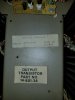
Sorry to hijack your thread but I picked one off the curbside and it’s missing the output transistors. Can you please tell the Motorola output transistor part numbers? Thanks in advance
 
Hi
I don't think you need those wires.

I think you should try and get it working before changing any parts. You could make a mistake or put in a defective part and now you have more problems to fix.

I can't imagine why the resistors would go bad ? Nearly all are Philips metal 5% very low noise and are high quality. Few are of old carbon - the resistors your wires are attached are carbon.
Frankly, I would not bother changing any unless burnt looking.

If you look closely at the transistors - you will notice many small signal start with a "B" number - these are from Europe and very special - low noise. Electrohome used to use a Siemens BC169C in their organs - and if someone replaced with a generic Japanese or US transistor - there was a lot more noise produced. Because of this - I wouldn't change any transistors unless you can get the originals. My guess is you will find the unit performs worse than now...transistors last a very long time.

I know electrolytics dry out - but once again - get it working perfectly before changing them....even then I wonder if it is worth it ?

Electrolytics need to be used to keep that dialectric film inside intact. In the old days (tube stuff) we used to "form" a new capacitor by turning it on and off a few times slowly to get it going. But then, the voltages then were 3 or 400 volts B+. I know Parker told me that they sometimes had a hard time sourcing Canadian made parts good enough (within cost limits) - he specified the best they could because he was competing against the best.

My 2100 is working after sitting here for 23 years doing nothing as well as my 1968 Ampex tube reel2reel, CD player, TV and a VCR and scope etc - I decide not to change all the caps until one breaks down. IMHO, changing all these parts diminishes the value - others for sure have different opinions. Besides, once you change all these parts - it doesn't look original anymore.

The connectors plugs are notorious for bad solder joints - as the years go by temperature changes break the solder up - there is not enough solder for the weight of the pins. On my 2100, the AM and FM didn't work because two of these pins solder connections were bad. The connectors themselves can use a bit of cleaning solution and moved to clean them.

The transistors sockets sometimes give trouble but not much. One of mine crackled - I sprayed some cleaner in it and inserted the transistor a few times and has been good since. Electrohome used these in TVs too to make servicing easier. A system is more reliable if soldered in.

Boards in most equipment are not meant to easily come out. Just part of the game I suppose.

Bob
Bob,

I have the schematics but all the transistors are all Planar part numbers, would you have a list of what their equivalents are in the usual Motorola or
Japanese types?
 
Back
Top Bottom