• The move to the new server is done. There are some software and database maintenance updates in process. This has us passing the hat around to help out. We appreciate any donations. Seriously, even a dollar helps. The payment page may be found here - https://www.audiokarma.org/support.html

HELP! Restoration Question Planar SR2100 Receiver like Marantz

Bob,

I have the schematics but all the transistors are all Planar part numbers, would you have a list of what their equivalents are in the usual Motorola or
Japanese types?
No worries at all. You may hi jack since it's all Planar 2100 related , I can learn too! I'd love a copy of the schematics, please. Where did you find it? Many thanks!
 
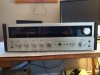
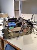
Happy to find this thread. I just picked one up today. No FM and blown channel that blows fuse is what I was told from seller. I have just started cleaning it up before working on it.
Figure I can learn and maybe help out.
 

Attachments

  • IMG_20230309_160255023.jpg
    IMG_20230309_160255023.jpg
    88.9 KB · Views: 12
  • IMG_20230309_162418494.jpg
    IMG_20230309_162418494.jpg
    136.5 KB · Views: 12
  • IMG_20230309_170218308.jpg
    IMG_20230309_170218308.jpg
    148.4 KB · Views: 13
Just finished working on another receiver and ready to tackle the Planar.
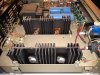
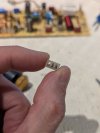
Quick check looks like I'll need two output transistors at least. Any idea what the substitute would be? I can't seem to find the info on these Motorolas. The 4 are all marked 601-34
I've looked through a few motorola pdfs and guess there is some MJxxx equiv?
 

Attachments

  • IMG_20230328_184122014.jpg
    IMG_20230328_184122014.jpg
    78.9 KB · Views: 5
I'm a little perplexed.
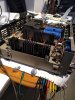
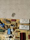
I pulled out the two shorted transistors and plugged in with DBT and all good. I was wanting to check bulbs and the FM issue and figured that the left channel would work. Plugged in headphones and both L/R are working. Tested for dc on speakers and that seemed ok, so plugged in a pair of minimus 7s. Both channels working. The SM doesn't seem to cover schematic for the amp section.
Anyone have an idea what is going on?
 

Attachments

  • IMG_20230330_170059003.jpg
    IMG_20230330_170059003.jpg
    116.9 KB · Views: 3
I'm going to order MJ15003 to replace the output transistors.
I would also like to replace the Q675 in the bias circuit.

I have KSC945YBU on hand that are 150mA Ic
I'm also going to order some 2N5551 which are 600mA Ic to be safe(r).
Can anyone tell from the schematic what would be required - part list identifies Q675 as small signal transistor.
Would running the collector leg through multimeter powered in circuit show that?
upload_2023-4-3_7-57-17.png
 
I'm not sure I can help you with any of your questions as I'm no expert. I think Bob would be best to answer if he's available.

My planar 2100 has some issues with the tuning gang (front end) and seems almost impossible to fix/get to as it has been soldered shut. Anyone here know anything about this?
 
Why do you think it's the gang?
My FM doesn't work and I'm in the middle of testing/replacing out of spec items on the tuning board but not the gang (yet).
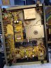
I believe the IC are ok for now - IC 101 is getting 8.15V on pin 7 (Vcc) and IC 102 is getting 7.46V on pin 9. I believe that they should get 12V. Will look at power supply after going through this board.
Any chance you can check your voltages on these with micro clip? And TPs 3 & 13 I think should have 12V.
 

Attachments

  • IMG_20230403_151141961_HDR.jpg
    IMG_20230403_151141961_HDR.jpg
    115.5 KB · Views: 5
I do not have those wires on my SR2100.

My resistors are 2.2K. These resistors are R540 and R640.
On my board it says (hand written) A06 and you have A04. Don't know what this means.
You have a real mystery here.

The audio you select with the SELECTOR SW501 switch go through these resistors via P513-5 and P315-6.
Then through all the TAPE selection and DUBBING switches and off to the volume and tone controls and then to the power amp.

Your wire appears to attach from the resistor and go to P516-5 which attaches to the Hi-Blend switch . This bypasses all the tape, volume and tone circuits..

I would expect this to cause the receiver to operate at full volume. Not sure why. I think I have it correct.
I attach some docs.
The small board looks OK.

What do you think ?
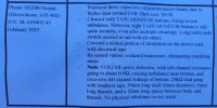
I really enjoyed reading this thread - thanks guys. I took this info from the "Service Guidelines" that came with my SR2080. The A04 etc refers to the chassis type. I believe A-04 = SR2100, and A05 = SR2080. I also attached a pic of the original "Power Performance Analysis" hand-written certificate that came with my 2080. It is pretty cool. Being rated at 40 watts, you can see that it actually puts out 66 watts at 1 khz. The best thing about these Planars (instead of sounding better than any Marantz I have heard), is that the Americans know nothing about them (just like Energy Pro 22 speakers). That way, us Canucks can keep buying them for 1/10th of what they are really worth.
I bought my 2080 from the original owner. This is the only work that has ever been done on this receiver (see repair invoice). I am still trying to source a replacement volume control (have to turn it 3/4 way to the right to get L/R balance). I just bought another Planar (2100), which is enroute as we speak.
 

Attachments

  • 20230813_155111.jpg
    20230813_155111.jpg
    36.3 KB · Views: 6
  • 20230813_155130.jpg
    20230813_155130.jpg
    111.9 KB · Views: 6
  • 20230813_161138.jpg
    20230813_161138.jpg
    82.7 KB · Views: 6
EUREKA!!!
I have finally gotten this damn receiver to work (mostly).
After much frustration I put it aside for over a year hoping to gain more experience orking on other equipment. The big issue I had was that I managed to get both channels working but could not set bias on the right channel. All transistors tested ok, and this unit has sockets to easily pull and swap L/R for testing. Replaced all caps, diodes, a bunch of resistors, 4 new Bourne pots and reflowed the board but still not able to adjust bias.
So, I started looking at it again and replaced a few more parts I had ordered last year. Still no bias adjust, so the last thing to do (should have been one of the first) was to check continuity for each transistor in socket to the board. Bingo!
Should have just soldered transistors direct to board, but it works now. Bias and offset dialed in.
Last thing to do is to get the old stereo light working. Time for a well earned beer and a good lesson of what to check early.PXL_20240727_192220722.jpgPXL_20240727_192235393.jpg
 
Well, I think I've gotten about as far as I can with this old girl unless I can ever acquire some gear cheaply enough for FM tuning adjustments. FM plays, but I can't get it in stereo, even after trying to replace the ICs and VR adjustments.

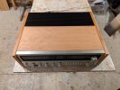
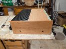
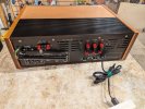
It has a new look now. The plastic grill has been painted black and the top/sides have been veneered in cherry. My son 3D printed the Planar logo plate that was missing. Just waiting on a new power switch cap to arrive.PXL_20240901_152538717.jpgPXL_20240901_152545561.jpgPXL_20240901_152557239.jpgPXL_20240901_152610751.jpg
 
Back
Top Bottom