

You are using an out of date browser. It may not display this or other websites correctly.
You should upgrade or use an alternative browser.
You should upgrade or use an alternative browser.
HELP Scott R-306 Receiver tuner problem
Register to hide this ad

I got just got this reciver. Everything works perfectly except FM is not detecting stereo. Can anyone help me please where to look. My experience with radio is limited.
Welcome to AK. You can try adjusting the variable resistor VR103, while tuned in to a strong station that you know to be broadcasting in stereo. Take note of the original position so that you can return the adjustment to that position if things don't work out. If you do find a range of positions where stereo starts to work, try to find the middle of the range.
In my opinion, this is the only chance for a DIY cure. If you are not confident that you can locate VR103, then I would strongly suggest that you don't try adjusting anything. You can find a service manual for the receiver at hifiengine.com, which may help you to locate VR103.
Cheers,
chazix
Hello and thanks very much for your reply. I do have the service manual and used it to repair the amplifier (had 4 bad transistors).Welcome to AK. You can try adjusting the variable resistor VR103, while tuned in to a strong station that you know to be broadcasting in stereo. Take note of the original position so that you can return the adjustment to that position if things don't work out. If you do find a range of positions where stereo starts to work, try to find the middle of the range.
In my opinion, this is the only chance for a DIY cure. If you are not confident that you can locate VR103, then I would strongly suggest that you don't try adjusting anything. You can find a service manual for the receiver at hifiengine.com, which may help you to locate VR103.
Cheers,
chazix
Unfortunately R103 has completely no effect.
I'm good with electronics but when it comes to radio i'm noob
Last edited:
Do i suppose to have 19khz signal on TP (pin 11 of the ic uln2244)? Because there no signal on this pin.chazix
Although pin 15 has 2.7volts that dose not change when adjusting VR103 as it should as i told you VR103 has absolutely no effect whatsoever.
Do i suppose to have 19khz signal on TP (pin 11 of the ic uln2244)? Because there no signal on this pin.
Although pin 15 has 2.7volts that dose not change when adjusting VR103 as it should as i told you VR103 has absolutely no effect whatsoever.
Yes, pin 11 is a test output for checking the 19kHz frequency.
Pin 15 is closer to the heart of the oscillator. It seems very strange that its DC point would not change when adjusting VR103. I should say that one possibility seems like the wrong pot is being adjusted, perhaps because of an error in the manual or my reading of it. What is the DC voltage on the lead of fixed resistor R139 that connects to VR103? (If the chip's oscillator is not running, then one would expect R139 and VR103 to act as a simple voltage divider for whatever DC voltage is on chip pin 15. If that isn't true, then there may be something wrong with one of those parts.)
Is there any appreciable DC voltage on board connection P114 ("OSC KILL")?
I disconnected the wires going to OSC kill and the mono/stereo to be sure they have no effect.
The wires going to OSC kill have 1.85 volts when switching to FM, 1.8v when on AM and 14 volts when switching to phono or aux
The signal on the IC pin one looks like audio with 38khz signal.
Changing VR103 value dose the following :
I checked C138 or 128 (390pf connected with the VR) and it is not bad at all.
The wires going to OSC kill have 1.85 volts when switching to FM, 1.8v when on AM and 14 volts when switching to phono or aux
The signal on the IC pin one looks like audio with 38khz signal.
Changing VR103 value dose the following :
- Pin 15 has a saw tooth signal that varies between 56khz and 66khz.
- The resistance between gnd and pin 15 varies between 22k and 26.3k.
- The voltage on pin 15 changes between 2.76 and 2.84 volts. Wich is hard to detect with my multimeter thats why i told you it has no effect.
I checked C138 or 128 (390pf connected with the VR) and it is not bad at all.
Pin 15 has a saw tooth signal that varies between 56khz and 66khz.
This seems like the juiciest clue, but I'm afraid I don't know where it leads.
That there is a sawtooth on pin 15 seems like it means that the chip's oscillator is working, but ideally its free-running frequency should be 76kHz (four times the expected 19kHz "pilot" signal). That the frequency varies with VR103 adjustment (if I understand your observations) seems like it means like the resistive parts of the oscillator circuit are OK. And the other observations don't point to a likely suspect for a low free-run frequency, in my view. (Though it could be that whatever you were using to check the frequency introduced extra capacitance that would slow it down. Hard to rule that out. It would have to be a fairly large value, 200-ish pF.)
If the chip's power supply is OK (pin 16, looks like it should be somewhere north of 12VDC), and if nobody cleverer than me comes along (there are plenty) with a better suggestion, then it might be time to replace the chip. But I'm not sure that's going to be easy. Besides the type numbers indicated on the schematic, I think LM1800 is another equivalent. A possible trustworthy supplier is ceitron, on web or on ebay.
Yes the LM1800 is Identical to this IC.
I tried other values of resistors (connected a 100K in parallel with the 22K) to get to the 76KHZ but this didn't get the stereo to work.
Again I removed C133 and got a distorted stereo and the stereo LED turnes on. I have no idea if this means anything.
I opened a technics radio to see if it uses the same IC but it uses another one
 that has vcc on pin 1 instead of the input signal.
I'll check another radio I have before ordering the IC.
Again I removed C133 and got a distorted stereo and the stereo LED turnes on. I have no idea if this means anything.
I'm not sure either. Pins 9 and 10 of the chip seem to be involved with the chip's "final decision" about whether to engage stereo mode or not. C133 is part of a filter which I assume stabilizes the decision-making so it doesn't vacillate rapidly between stereo and mono when conditions are on the fringe.
I'll note that board terminal P113 being pulled low can disable stereo, so might be worth checking that.
But neither of the above would account for the chip's oscillator being so far off from its proper frequency.
Now, the components connected to chip pins 13 and 14 are part of another filter, one that regulates how quickly the oscillator frequency can change. It's possible that a fault in those components (probably the capacitors, especially if they are electrolytics) could account for the frequency being so far off.
I got the LM1800 (Chinese clone) replaced the original and it is working perfectly. Beautiful clear sound .
I just tested the speakers output for DC Because it is making a loud click when turned on. With volume set to zero there is a DC 150mV on one side and 20mv on the other side (the side where I replaced the transistos). I think this is acceptable or is it high ?
I can't see a biasing adjustment variable resistors on this model so don't know how this can be adjusted if it does need adjustment.
I just tested the speakers output for DC Because it is making a loud click when turned on. With volume set to zero there is a DC 150mV on one side and 20mv on the other side (the side where I replaced the transistos). I think this is acceptable or is it high ?
I can't see a biasing adjustment variable resistors on this model so don't know how this can be adjusted if it does need adjustment.
Last edited:
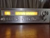
Thanks a lot chazix for your help.
I can't see a biasing adjustment variable resistors on this model so don't know how this can be adjusted if it does need adjustment.
Congratulations on your success with the stereo decoder!
150mV of DC offset would cause me to worry, though it is not enough to damage anything. You are correct about the lack of adjustments. The offset is strongly dependent on the matching of the two transistors in the first stage of the power amp circuit, Q501 and Q502 (or Q511 and Q512, depending on which channel is involved). If you want to pursue an improvement, you could consider replacing the pair of transistors in the high-offset channel with a pair of low-noise NPN transistors with voltage ratings of at least 50V. In the USA, KSC1845 would be a typical choice, but I don't know if those are readily available for you.
(A side note: You mentioned "biasing adjustment". Although it may be a linguistic difference, that is not how most USA readers would describe an adjustment that affects DC offset voltage. In many power amplifiers (but not yours), there are separate adjustments for DC offset and what is usually called "bias" or "idle current". The bias adjustment would control how much current flows through the output transistors when there is no audio signal. That adjustment is different from, and mostly independent of, the DC offset adjustment.)
Cheers,
chazix

