• The move to the new server is done. There are some software and database maintenance updates in process. This has us passing the hat around to help out. We appreciate any donations. Seriously, even a dollar helps. The payment page may be found here - https://www.audiokarma.org/support.html

Help with an SX1500 Receiver.

Seth Wolpert

New Member
Hello all. Is there anyone there who knows this receiver? I'm trying to repair the power output stage. One channel is blowing fuses. Both output transistors tested bad and I replaced them, but the problem persists. Since then, I have replaced the other three transistors and all of the electrolytic capacitors. Still no luck. All
transistors I installed tested good.

My approach to the repair is to run the main power through a variac and gradually turn up the voltage until I
see current draw through the fuse fitting approaching about a half an amp. The working channel is only
drawing a few milliamps at that point. I'm then probing all of the DC bias points, comparing the working to
the non-working channel. Only one circuit node is showing any difference-about one volt. Is the use of a
variac like this a sound approach?

I've tried adjusted the bias. The current draw changes, but is still way higher than the working channel.
This thing is kicking my butt. Any help would be highly appreciated.
 
Register to hide this ad
OK, so we know which amp side is having issues. That helps. Look for burnt resistors on that channel. Test any large white resistors as well. The trimmers may need replacing as well. Can you post a few pictures of the amp board, especially the bad side?
 
Before your next varac run, turn down vr(3/4) to zero ohms, and check that their circuit with the STV-3 is uninterrupted - from Q5 base to Q7 base.
if those thermal diode connections break /go open circuit the amp turns on HARD.
a dirty trimmer can do the same. HUGE idle currents.
caution - the leads on the STV-3 part are fragile and break easily. do not bend them within 1/4 inch of the component body.

Also check the 0.5 ohm and 150 ohm resistors They are directly in line for damage with the type of fault you have described.

as long as R23, R25, R27, R29, Q5 & Q7 are undamaged,
the amp can (WITHOUT ANY LOAD!!!) be operated without the Q9 & Q11 outputs installed
this will stop the huge currents flowing, and allow examination of their "operating instructions" in the form of the base (to emitter) voltage.
 
i had trouble with the stv3 that was blowing the fuse on one channel of my 1500td and it took me quite a while to get on to it. its easy to check if you lift one leg and use the diode test it will read like 3 diodes in series (which is what it is) in the forward direction and open if you reverse the meter leads. if its bad you will have trouble finding one but you can make one with 3 1n4007's stacked and connected in series and epoxied together in the smallest package possible. that part isnt shaped like the later "horseshoe" ones its been 5 years i dont recall how it was mounted to the heatsink
 
Last edited:
Wow. Thanks for your very informative replies. The STV3 sounds like it could be the problem, and I will check it ASAP.
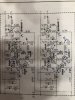
In reply to your feedback, here are three images. The first is a diagram of the amplifier board and the DC readings I
get with the variac at about 1/3 of full voltage. Good channel on the right, bad channel on the left. The only significant
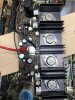
difference I see is on the base of Q9 versus Q10. The second and third are photos of the board. One of the 150 ohm
resistors was burned out and I replaced it. It's the only 5% 1/2W resistor on the board. I also replaced one of the output
capacitors with another with the same value and voltage rating, but I am not confident that it has the same ripple current,
but that wouldn't cause the fuse to blow, so I'll get to that later.
resistors was burned out, and I replaced it. You can't miss it. It's the only half-watt IMG_0501.jpeg IMG_0502.jpeg IMG_0503.jpeg
 
A brief follow-up on the design. There are four stages, and the first two are common emitter configuration with feedback
from the output to R12. The third stage looks like push-pull, class AB, but the output stage almost looks like class A with
Q9 as the output stage and Q10 as a current sink. Am I on the right track?
 
I'm seeing STV-3's for sale on eBay. At $16, they cost much more than a trio of 1N4007s, but if they work, it's worth it.
Any warnings about them?
 
stv's rarely give problems (other than broken leads)

if you gotta fool around, make a string of 1n4007's - and THAT voltage may be too much.

A brief follow-up on the design. There are four stages, and the first two are common emitter configuration with feedback
from the output to R12. The third stage looks like push-pull, class AB, but the output stage almost looks like class A with
Q9 as the output stage and Q10 as a current sink. Am I on the right track?

not bad...
Q10 is the other channel, you mean Q11, right?
Q9 & Q11 are push pull, you have to remember that both are npn and need 0.6v base to emitter,
as opposed to a PNP Q10 which would need -0.6v base to emitter.
thus the 10 ohm and 150 ohm resistors of that driver stage are swapped.
 
I understand what you're saying. It's just that most push-pull stages I've seen use npn for push
and pnp for pull. The pull down transistor in this circuit draws the output signal off the collector,
which is inverted. In a conventional push-pull, the pnp emitter would be the output, which is not
inverting. That's why this design appears different to me.

Other follow-ups: I pulled the SVT-3. The meter on the working side reads about 1.7V. The
bad side read about 1.9 at first, but then read open. I may have caught its dying throes. I've
ordered a replacement.

The trim pots checked out fine, and I cleaned them anyway.
 
I understand what you're saying. It's just that most push-pull stages I've seen use npn for push
and pnp for pull. The pull down transistor in this circuit draws the output signal off the collector,
which is inverted. In a conventional push-pull, the pnp emitter would be the output, which is not
inverting. That's why this design appears different to me.
.

Dual NPN outputs happened because the corresponding (mirror image) PNP transistors were not yet ready for the world.
 
no issues that im aware of.mine in my workshop 1500td. has been working for 3-4 yrs now and believe me its hot here. work out the connections for series and stack three diodes with a dab of jb weld and let it cure before you solder the series. i deliberately over glued it and laid it on wax paper and sanded the epoxy flat on the bottom. like i said i dont remember how it mounted and its important to remember it needs to be in intimate contact with the heat sink i do remember using thermal conductive wakefield compound. i also gutted the original trimmers and used them as mounts for new multi turn trimmers at the same time. it will certainly make your life easier as you arent likely to find trimmers that fit the board spacing. an alternative i guess is to buy a style that has LONG leads and mount them off the board. you would still want the long leads even if using the originals as mounts but i found that the GUN REEL version was either not made in all possibilities by bourne or mouser didnt stock them. so in one set i had to extend the leads.
 
Last edited:
Other follow-ups: I pulled the SVT-3. The meter on the working side reads about 1.7V. The
bad side read about 1.9 at first, but then read open. I may have caught its dying throes. I've
ordered a replacement.

Hopefully the part is not faulty. Some DVMs apply too low of a voltge to turn on 3 pn junctions. To be sure, you should test the STV-3 using a 9V battery and a 1K resistor in series with the diode. This will limit the current to nearly 7mA. Then use your DVM to measure the voltage drop across your STV-3H. If your diode has a paint dot in its body it shows the rank which correspond to the range of forward voltage drop (see here for the ranks).
 
Thanks, Jose. My DMM uses a 9V battery, and it was able to detect the difference between the working STV-3 and the suspicious one, but I'll give this a try. I don't recall seeing any painted dots on the package. If the difference between the old and the new is small, I assume it can be adjusted with the bias.
 
not that it matters much. while the differences are well noted by me, it hardly matters if the part cant be sourced anymore. mine didnt reveal itself as failed at first it took a while. the set worked for about 6 mos and would blow a fuse whenever it deemed fit to do so. it was really maddening to say the least. i originally checked the stv's on both channels. it wasnt until it decided to "retire" permanently was i able to nail it. heretofore my experience with diodes was either they work as intended or they are open. experience is what we get when outcomes arent what we are expecting.
 
Last edited:
I ordered a used STV, but I'm not confident that it will be long-term reliable. I'll run the receiver for a few
hours before I return it to the customer. If it fails again, I'll build a 3-diode stack, as suggested earlier in
this thread.
 
Made progress on the amplifier board. The 50-ohm trim pot was open, which threw the bias off and fried
the output transistors. I couldn't find a new 50-ohm trim pot, so I installed a 50-ohm potentiometer in its
place. It now plays, but the output transistors of the repaired channel are running fifty degrees warmer
than their counterparts under light loading (headphones with 30% volume). When I apply a 1kHz triangle
wave, the output amplitudes are equal, but the repaired channel is more sinusoidal. It's lost its higher
frequency response. Adjusting the bias doesn't have any effect. Any recommendations on where to
look next. I've already replaced all of the electrolytic capacitors except for the output capacitor and
replaced five out of six transistors, plus the STV-3 diode stack. Please ignore the vertical scale on
the scope. It didn't know I was using a 10x probe.
IMG_0531.jpeg
l
 
Check every transistor (remove it !!) in the duff channel for function, and check every resistor (one leg lifted) for the correct value.

There really aren't that many....

upload_2022-7-18_13-15-18.png
 
Back
Top Bottom