
• The move to the new server is done. There are some software and database maintenance updates in process. This has us passing the hat around to help out. We appreciate any donations. Seriously, even a dollar helps. The payment page may be found here - https://www.audiokarma.org/support.html

Help with C2 Basic Balance Pot

derekva

This ain't no picnic...
Subscriber
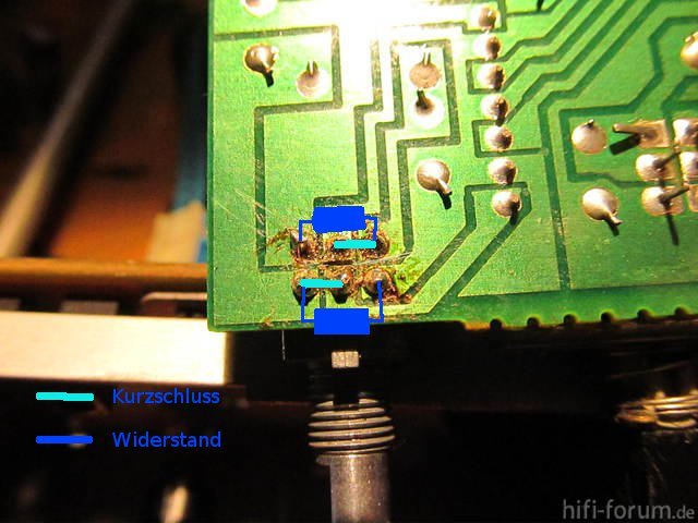
I have a C2 Basic with a broken balance pot. While I understand the tried-and-true modification of bridging the connections with 180k resistors (http://www.audiokarma.org/forums/showthread.php?t=509349), I am considering trying to replace the pot with a 200k Bournes linear-taper. The pot will fit the circuit board and should be wired up properly given that the circuit board is inversely wired (e.g. Channel A, pin 1 and Channel B, pin 3 have the same circuit path, while Channel A, pin 3 and Channel B, pin 1 also have the same circuit path). I will, unfortunately, have to modify the shaft as I can only find this pot with a knurled shaft However, I have some questions:

  • Am I correct in assuming that the value of the pot should be 200k (as close to 180k as you can get)? This would mean at center-detent (balanced), the resistance between each side would be 100k, which is slightly more than 1/2 of the 180k value of the resistor mod.
  • Would this translate to lower output volume from each channel when centered?
  • Am I even correct in assuming this should be a linear taper?
A photo of the circuit and the resistor mod are below:

basic-c2-balance-poti_391448.jpg


uberbruckung-des-balance-regler-im-kenwood-basic-c2_255808.jpg


finale001255882.jpg


Thanks in advance,

-D
 
Last edited:
Register to hide this ad
Seriously...nobody? Damn, Kenwood gear really *is* arcane.

Well, I'm gonna give it a shot and see how it turns out. If worse comes to worse, I've wasted $2.15 and about 15 minutes of my time.

-D
 
Where are you planning to source the replacement from?

Most balance pots are zero ohms at the center position. If your replacement works that way, the value of the pot at either end is not terribly important.
 
You are the guinea pig. I have the same issue with my C2. I don't think that the pot value will matter very much. It depends on if the pot is delivering a voltage signal downstream (no difference) or a current signal (slight difference).
 
Well...it was of a mixed success. Given that a linear taper is about as close to a 45-degree angle as possible, the amount of volume at 'balanced' is about 50% of what it is when cranked to either extreme. What I really need is an inverse log potentiometer (a.k.a. 'reverse log', 'antilog', or 'C-taper'), and while Bourns and Alps list them in data sheets, nobody carries them. :sigh:

The end result is that I'll be replacing the pot with a pair of 180k resistors.

-D
 
OK, since I'm a whole lot green on this stuff, what seems to be the problem? Why is this control so hard to find or cobble a replacement for?

Aren't there a bazillion devices out there with Balance circuits? Intuitively, I'd think there would be plenty of pieces to fit, but obviously that's not the answer.

Then again, it's impossible to find a Power switch for a NAD 3020 too...:dunno:
 
The pot itself is tiny, and soldered directly to the PC board. There's no leeway to install some jackleg device to just 'get it working'...the replacement device has to be pretty much the same damn thing as the original, and I dunno where to get anything that might work.
 
The pot itself is tiny, and soldered directly to the PC board. There's no leeway to install some jackleg device to just 'get it working'...the replacement device has to be pretty much the same damn thing as the original, and I dunno where to get anything that might work.

Makes sense to me :thmbsp:

Thanks EW!

I gotta haul mine out and check it, but it seemed like the last time I used it I was screwing around with I was A/B'ing something by rolling the Balance pot and it wasn't cooperating...
 
The pot itself is tiny, and soldered directly to the PC board. There's no leeway to install some jackleg device to just 'get it working'...the replacement device has to be pretty much the same damn thing as the original, and I dunno where to get anything that might work.

The sad thing is that you can find something "close" from a dimensional and/or resistance standpoint, but there's always something a bit off about it (flanged instead of flatted shaft, shaft 5mm too short, wrong taper, etc.). I wonder what a Bourns minimum order would be...perhaps if it is something reasonable like 20 or so, I should try and set up a group buy. The specific model I would need would be designated as PTD902-1220F-C204 (200K - as close as you can get w/ Bourns).

-D
 
So I shot an email off to Bourns. If they can do a small run (say 20), I'll let everyone know and perhaps I can coordinate a group buy on the BarterTown or D&S forums.

-D
 
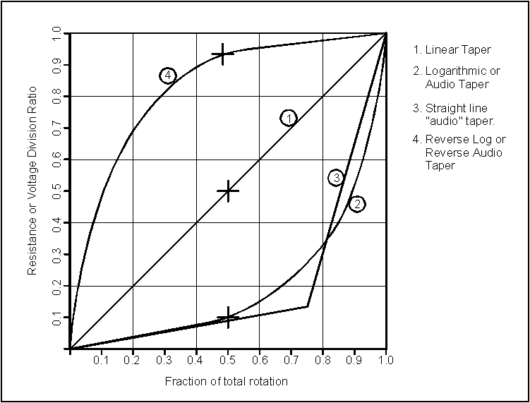
We'll see what happens. I'm not sure if the C-taper will even help as it appears to be an inverted anti-log taper. What the taper needs to look like is labeled as (4) in the image below:

pottaper.gif


Perhaps I can get someone clever at Bourns to help me with this.

-D
 
The taper is not terribly important (and I'd prefer a linear taper for balance), but what IS important is that the device is meant for use as a balance control, and the center position equates to zero resistance.
 
The taper is not terribly important (and I'd prefer a linear taper for balance), but what IS important is that the device is meant for use as a balance control, and the center position equates to zero resistance.

OK. I'm confused. I decided to go to the source and take apart my (working) C2 Basic and take measurements on the potentiometer. I'm making the following assumptions based upon the schematic above:

  • VR1-a is the right channel (front row of pins from edge of the circuit board)
  • VR1-b is the left channel (back row of pins from edge of the circuit board)
  • Pin 1 (VR1-a) and Pin 3 (VR1-b) are ground
  • Pin 2 is wiper (output) for both VR1-a and VR1-b
  • Pin 3 (VR1-a) and Pin 1 (VR1-b) are inputs
When cranked over CW (full right):
  • The right channel measures 42kOhms between input and ground
  • The right channel measures zero Ohms between input and wiper
  • The right channel measures 42kOhms between wiper and ground
  • The left channel measures 190kOhms between input and ground
  • The left channel measures 190kOhms between input and wiper
  • The left channel measures zero Ohms between wiper and ground
When cranked over CCW (full left):
  • The right channel measures 190kOhms between input and ground
  • The right channel measures 190kOhms between input and wiper
  • The right channel measures zero Ohms between wiper and ground
  • The left channel measures 42kOhms between input and ground
  • The left channel measures zero Ohms between input and wiper
  • The left channel measures 42kOhms between wiper and ground
When centered:
  • The right channel measures 42kOhms between input and ground
  • The right channel measures zero Ohms between input and wiper
  • The right channel measures 42kOhms between wiper and ground
  • The left channel measures 42kOhms between input and ground
  • The left channel measures zero Ohms between input and wiper
  • The left channel measures 42kOhms between wiper and ground
So at center position, we're looking at zero resistance on both channels between the input and the wiper, which would meet your base criteria for a balance pot. However, what the heck kind of taper would correspond to the other measurements? Log? Antilog? AntiChrist? And what should the correct value be? 190kOhms (or 200kOhms since we're working within what's available)?

Thanks,

-D
 
Last edited:
The 42K reading is probably the input 'resistance' of the next stage. In any event, it's hard to determine the taper with only readings from the center and two extremes. You'd need to plot resistance vs angle of inclination. Not worth the trouble. How often do you need a balance control anyway?
 
How often do you need a balance control anyway?

I only use one generally to measure input or output differences and that's at full lock one way or the other, so it would seem to me that the curve of how it gets there isn't important.
And I don't measure those that often either, like a couple times a decade. My current preamp has no Balance on it at all.

While it WOULD be nice to have a working Balance, the resistor jumpers should get the units working for 99.9% of the users and applications out there.
 
I only use one generally to measure input or output differences and that's at full lock one way or the other, so it would seem to me that the curve of how it gets there isn't important.
And I don't measure those that often either, like a couple times a decade. My current preamp has no Balance on it at all.

While it WOULD be nice to have a working Balance, the resistor jumpers should get the units working for 99.9% of the users and applications out there.

Probably right, but sometimes it is valuable to have a balance control.

-D
 
When everything was said and done, since there is no need for attenuation, I simply jumpered the inputs to the outputs (e.g. no 180k resistor tying the input to ground). Sounds great with no loss of gain.

-D
 
Back
Top Bottom