

You are using an out of date browser. It may not display this or other websites correctly.
You should upgrade or use an alternative browser.
You should upgrade or use an alternative browser.
Help with C2 Basic Balance Pot
- Thread starter derekva
- Start date


Sorry to see getting a new pot didn't work out... Since you know a hell of a lot more than me... Why the 180k resistors? I just put them there because that's what those German guys did... But if a simple jumper works I wonder why that was recommended.
Well, if you look at the resistance charts below, what you end up with is a jumper between the input and output (wiper) to correspond to the zero ohms (straight wire) when the balance pot is centered. The 180k resistor goes between the input and ground (or wiper and ground) to approximate the load seen when the balance control is panned hard left or hard right. However, when centered, the load between input/wiper and ground is only 42kOhms. I came to the conclusion that the important part of the signal path is input to output and that the ground path is more-or-less irrelevant. I suppose if I wanted to square the circle as it were, I'd put 42k resistors between input and ground, but I don't think there's really a need.
I'm sure EW will disabuse me of this notion if I'm talking out of my ass. :thmbsp:
-D

janikphoto
Lunatic Member
So, does my issue here: http://www.audiokarma.org/forums/showthread.php?p=7564854#post7564854 sound like the balance pot, as well? I'd love to use this thing. It'll be in a room that balance adjustment would be nice, but not a deal-breaker.
bentoronto
New Member
I think derekva has it about right. Just a jumper from input to wiper (middle pin). But prolly prudent to have another resistor from wiper to ground in the vicinity of 180kOhms give or take 50k. (A DIYer can quickly establish which pins connect to the ground network on the printed-circuit board.)
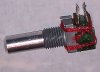
When I got to my balance control, turned out a previous owner had a go at it. The wipers were glued OK but the pins used to hold it together were too loose... as seems inevitable when you play with that method.
Using a small drop of contact cement and a few turns of sewing thread made the balance control pieces tight. Turns of thread, like a constrictor snake, can produce substantial force. See the picture with red thread.
Sadly, even with it tight and seeming to test well on the bench, still short of 100% when installed.
But I have many volume controls upstream and downstream in my system (I'm a big believer in the value of "gain management" as are other Behringer DSP owners). So a balance knob is nice but superfluous.
Anybody ever found a source for buying replacement controls?
Ben
When I got to my balance control, turned out a previous owner had a go at it. The wipers were glued OK but the pins used to hold it together were too loose... as seems inevitable when you play with that method.
Using a small drop of contact cement and a few turns of sewing thread made the balance control pieces tight. Turns of thread, like a constrictor snake, can produce substantial force. See the picture with red thread.
Sadly, even with it tight and seeming to test well on the bench, still short of 100% when installed.
But I have many volume controls upstream and downstream in my system (I'm a big believer in the value of "gain management" as are other Behringer DSP owners). So a balance knob is nice but superfluous.
Anybody ever found a source for buying replacement controls?
Ben
Attachments
Last edited:
janikphoto
Lunatic Member
No source, but no my output RCA's are acting up. I'm gonna crack my unit open and look at them, why they are giving me grief now.
janikphoto
Lunatic Member
OK, so I took it out of the system, opened it up, re-soldered the rca output joints, and then put some high torque silicon around the rca assembly to help hold it better. It seemed to wiggle too much on the board, and I didn't have any jb weld handy, so I hope this rtv provides enough support to help hold it in place better. I also re-soldered the phono and CD rca inputs, since they are used on the unit. No reason not to, since it was already open. I'm testing it now, and the channels aren't cutting out yet. It was having one or both drop and I've have to wiggle the rca to bring it back. I tried several different cables, so my assumption was the unit and not bad luck of three or four bad cables in a row!
I guess to sum things up, if you are doing the balance knob fix, you mind as well check for cold solder joints on the RCA's while you're at it.
I guess to sum things up, if you are doing the balance knob fix, you mind as well check for cold solder joints on the RCA's while you're at it.
OK, so I took it out of the system, opened it up, re-soldered the rca output joints, and then put some high torque silicon around the rca assembly to help hold it better. It seemed to wiggle too much on the board, and I didn't have any jb weld handy, so I hope this rtv provides enough support to help hold it in place better. I also re-soldered the phono and CD rca inputs, since they are used on the unit. No reason not to, since it was already open. I'm testing it now, and the channels aren't cutting out yet. It was having one or both drop and I've have to wiggle the rca to bring it back. I tried several different cables, so my assumption was the unit and not bad luck of three or four bad cables in a row!
I guess to sum things up, if you are doing the balance knob fix, you mind as well check for cold solder joints on the RCA's while you're at it.
I have not seen a problem with cold solder joints on either C2 I've had at my house, but I did see this problem with my Denon PRA-1000. I'm not surprised since these preamps were made around the time of the dawn of wave soldering.
-D