• The move to the new server is done. There are some software and database maintenance updates in process. This has us passing the hat around to help out. We appreciate any donations. Seriously, even a dollar helps. The payment page may be found here - https://www.audiokarma.org/support.html

Help with ground in a SET amplifier from Japan

alanbrain

AK Subscriber
Subscriber
Hi,

I am not sure this is the best place to ask for your help with a couple of questions. So, please let me know if I should post this in a different sub forum.

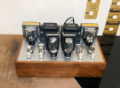
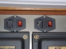
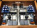
It is about how ground is managed in Japan, because I have a SET amplifier from Japan. I bought a 100V DIY Japanese dual mono SET amplifier that has a couple of 717As per channel driving either a 300B, 2A3, or a 45. The amplifier has fixed bias, hum pots, and a knob to select the operating point for either a 300B, 2A3 or 45 tube. The amplifier has two IECs in the back, one for each channel and each IEC has 3 prongs.

You can see all that in the pictures attached. Unfortunately, I do not have the schematics of the amplifier.

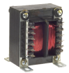
I am going to use the amplifier in the United States. Surely, the amplifier, being made in Japan, works with 100V and either 50hz or 60hz. The power transformers are Sansui P- 44B which I believe can work either with 50hz or 60hz. So, HZ should not be an issue.

These are my questions:

1. For the voltage and ground issue, I am planning to use this step down transformer, which has 2 outlets for 100V, in 1600 Watts, which should be more than enough even with the 300Bs in place. But, I am a bit confused with the ground issue. Clearly the IECs in the amplifier have 3 prongs, and the IEC outlet in the step down transformer linked above, has also 3 prongs. So, I was planning to simply use a common USA power cord from the IEC in the amplifier to the step down transformer outlet, is that OK to safely handle the ground or am I missing something? I am not sure how the ground is handle in the amplifier, but maybe someone can understand that by looking at one of the pictures attached that shows the wiring.

2. The amplifier also has 2 hum pots. Regarding the hum pots, I was planning to do what I usually do which is: Let the amp warm up for at least 30 sec without music, turn the hum pots clockwise until I hear the hum increase. Then turn counter-clockwise until the hum decreases and then increases again to about the level
where I stopped the clockwise rotation. And then, set the pot to the middle of these two positions. Is that OK or am I missing something?

Any help is greatly welcome.

Thanks in advance!

Alan
 

Attachments

  • 1.jpg
    1.jpg
    160.1 KB · Views: 80
  • 2.png
    2.png
    893.5 KB · Views: 77
  • 3.png
    3.png
    793.7 KB · Views: 74
  • 4.jpeg
    4.jpeg
    115.3 KB · Views: 64
  • 5.jpeg
    5.jpeg
    145.1 KB · Views: 72
Register to hide this ad
WOW~!

I am jelling at your Sansui transformers and amazing looking amplifer!

Yes, Ground should be handled OK, Setting the Hum pots is standard but can change depending on preamp and source connections.

Adjust normally but test with all sources.

50/60 Hz will not be an issue as the transformers are wide banded.

Future reference, Many 100 volt Nippon power transformers have a 120 volt tap inside the case.

Good luck, Once again I am very jealous of your amazing amplifier...

Buck
 
Last edited:
The hum pot adjustment is OK. Two things I would want to know about the primary wiring. First, can you confirm with an ohmmeter that the third wire (ground) prong at the transformer's power cord is connected to the third wire connection in its IEC outlet socket? Then you need to confirm that the third wire connections at the IEC sockets in the amp are connected to chassis ground. I'm sure all this will be fine, but it needs to be checked. A second issue would be whether Japan treats hot and neutral the same as in the U.S. They're supposed to be the same, but I would want to confirm that neutral and hot at the wall outlet end up in the same positions at the amplifier IECs after going through the transformer and cables.

As a side note, I would look for a way to avoid sending power through a step down transformer if possible (and I sure wouldn't buy a Chinese transformer on Amazon for this). Like @Buck Rogers said, maybe the transformers in the amp can be rewired. Another option would be a 20V bucking transformer. This will probably present a lower impedance to the AC input of the amplifier than an actual step down transformer. Here's some theory if you're into DIY. Figure 4 shows the right way to get this done:

Bucking Transformers (Elliot Sound Products)

Jack
 
The Sansui P-44B has a 110V option.

0imF7lOl.jpg
 
WOW~!

I am jelling at your Sansui transformers and amazing looking amplifer!

Yes, Ground should be handled OK, Setting the Hum pots is standard but can change depending on preamp and source connections.

Adjust normally but test with all sources.

50/60 Hz will not be an issue as the transformers are wide banded.

Future reference, Many 100 volt Nippon power transformers have a 120 volt tap inside the case.

Good luck, Once again I am very jealous of your amazing amplifier...

Buck

Thanks @Buck Rogers and @zackthedog for the kinds words about the amplifier. I bought it in Yahoo Japan Auction through an agent. I mostly bought for its dual mono configuration and the selection of transformers.

The hum pot adjustment is OK. Two things I would want to know about the primary wiring. First, can you confirm with an ohmmeter that the third wire (ground) prong at the transformer's power cord is connected to the third wire connection in its IEC outlet socket? Then you need to confirm that the third wire connections at the IEC sockets in the amp are connected to chassis ground. I'm sure all this will be fine, but it needs to be checked. A second issue would be whether Japan treats hot and neutral the same as in the U.S. They're supposed to be the same, but I would want to confirm that neutral and hot at the wall outlet end up in the same positions at the amplifier IECs after going through the transformer and cables.

As a side note, I would look for a way to avoid sending power through a step down transformer if possible (and I sure wouldn't buy a Chinese transformer on Amazon for this). Like @Buck Rogers said, maybe the transformers in the amp can be rewired. Another option would be a 20V bucking transformer. This will probably present a lower impedance to the AC input of the amplifier than an actual step down transformer. Here's some theory if you're into DIY. Figure 4 shows the right way to get this done:

Bucking Transformers (Elliot Sound Products)

Jack

@TriodeLuvr , thanks for the detailed advice. I will check tomorrow if the ground at each transformer is connected to the third wire in each respective iEC, and I will also check if that is connected to the chassis ground.

I will also check the hot and neutral configuration in the cables going from the power transformers to each IEC in the amplifier. Although, I am not fully sure how I will check this without plugging the amplifier. If you have any ideas, please let me know. I have a multimeter and I know how to use the basic functions, and I know how to solder, but I am still very basic for high voltage related DIY.

Thanks for the bucking transformer suggestion also, I may go that route at a second stage. I agree that, ideally, I would prefer to avoid sending power through a step down transformer from China, but I did not find many more easily available. I will check on Yahoo Japan Auction. If anybody has suggestions for a good external step down transformer, please let me know.

The Sansui P-44B has a 110V option.

0imF7lOl.jpg

@opnly bafld thanks for checking about that 110v tap in the P-44B, would that tap be enough (without a bucking transformer) considering that USA voltage is closer to 120v?

Alan
 
@opnly bafld thanks for checking about that 110v tap in the P-44B, would that tap be enough (without a bucking transformer) considering that USA voltage is closer to 120v?

Alan

Did you receive a schematic with voltage references for the amplifier?
If you are aware of the danger when poking around high voltage and are comfortable checking voltages you can see what the filament/heater voltage is to give you an idea if they are close to spec or still too high using the 110V taps.

I have a 110V transformer amplifier and my wall voltage runs high (123-124V) so I use a bucking transformer that brings it down to @114V so the amplifier voltages are within tolerance for the parts.
 
Last edited:
would that tap be enough (without a bucking transformer) considering that USA voltage is closer to 120v?
No, you'll still need to drop the voltage. About the hot/neutral thing, one way to check is to use your voltmeter to test the AC wall outlet. One of the slots will measure 120VAC to the ground prong. That's the hot wire. The other slot should measure 0V. That's neutral. Once the step down transformer is connected to the wall, you should measure the same relationship at its IEC outlet. The only difference is that the ground connection is a slot rather than a round socket. This will confirm that everything from the wall to the output of the step down transformer is OK. We have to assume the AC cable plugged into the transformer is also OK, so the only thing left is the wiring inside the amplifier. It might be a little tricky without a schematic, but generally speaking, there shoujld be a wire connected to the hot terminal of the IEC connected directly to a fuse holder. From there, it should travel to the power switch and anything that's supposed to be powered all the time, like a microprocessor or remote control board. In your amp, the IEC is integrated with the fuse holder and power switch. Once you know which input pin of the IEC is hot, it should be possible to determine the rest with an ohmmeter. I know it's a bit of trouble opening the amp for this, but I think it's worth doing.

Jack
 
Did you receive a schematic with voltage references for the amplifier?
If you are aware of the danger when poking around high voltage and are comfortable checking voltages you can see what the filament/heater voltage is to give you an idea if they are close to spec or still too high using the 110V taps.

I have a 110V transformer amplifier and my wall voltage runs high (123-124V) so I use a bucking transformer that brings it down to @114V so the amplifier voltages are within tolerance for the parts.
Thanks @opnly bafld
Let´s see if I dare to implement the bucking transformer option!
I know my way with a multimeter, but still sort of shy dealing with high voltages. I am buying an outlet polarity tester to help me a bit with all this.
 
No, you'll still need to drop the voltage. About the hot/neutral thing, one way to check is to use your voltmeter to test the AC wall outlet. One of the slots will measure 120VAC to the ground prong. That's the hot wire. The other slot should measure 0V. That's neutral. Once the step down transformer is connected to the wall, you should measure the same relationship at its IEC outlet. The only difference is that the ground connection is a slot rather than a round socket. This will confirm that everything from the wall to the output of the step down transformer is OK. We have to assume the AC cable plugged into the transformer is also OK, so the only thing left is the wiring inside the amplifier. It might be a little tricky without a schematic, but generally speaking, there shoujld be a wire connected to the hot terminal of the IEC connected directly to a fuse holder. From there, it should travel to the power switch and anything that's supposed to be powered all the time, like a microprocessor or remote control board. In your amp, the IEC is integrated with the fuse holder and power switch. Once you know which input pin of the IEC is hot, it should be possible to determine the rest with an ohmmeter. I know it's a bit of trouble opening the amp for this, but I think it's worth doing.

Jack
Thanks Jack. I will do that.

I just got feedback from a friend of mine who is using the same UMI transformer with a EL34 amplifier and he told me that as long as I get a transformer that is 2X what the amplifier may need, it is a good entry point. He had it for months with no issues, no hum at all. But, following on your advice, he also told me that it is good only as an entry level option and that later I can move to a customized step down, or a military surplus variac. One good thing of this UMI is that it has two outlets, which helps because I can directly connect the two power cords from the amplifier. UMI is not as bad as some other chinese products, they actually have an audio signal transformer that is very well respected in Asia.

I think I will go the UMI route for now, and then, down the road, look for a much better option. But I will check the polarity and the ground connection inside the amplifier first.

Also, just to be sure, I will run an polarity tester in my wall outlet and then in the step down transformer, just to be sure that the UMI is actually handling ground properly.

One last question, if I may, the amplifier came without any bottom plate, is that something I should be worried about regarding ground?

Alan
 
Alan, do you know when the amp was made?

I see the Sansui output transformers and know they are very nice for SET amps like these.
The Japanese audiophile community in the 90's was crazy for building SET amps like these using the earliest tubes.

They are rare and are great finds
I, myself have a 2A3 SET 100v Japanese amp
The wiring is run like a ZEN garden
I just run it off a variac

enjoy
 
Last edited:
Did you receive a schematic with voltage references for the amplifier?
If you are aware of the danger when poking around high voltage and are comfortable checking voltages you can see what the filament/heater voltage is to give you an idea if they are close to spec or still too high using the 110V taps.

I have a 110V transformer amplifier and my wall voltage runs high (123-124V) so I use a bucking transformer that brings it down to @114V so the amplifier voltages are within tolerance for the parts.
I forgot to reply to the schematic question. Unfortunately, the seller did not offer a schematic. And, since I managed the purchase through Buyee agent, I could not ask the seller any questions. I know that the amplifier is fixed bias though because a direct buyer from Yahoo Japan Auction asked that specific question. I also know that the amplifier has those 2 knobs: one clearly labeled for operating point for different tubes (300B, 2A3, 45) and one knob that I believe is a hum pot.
 
Again, first thing I do is make sure this is not a revived 11 year old thread...okay its now!

Alan, do you know when the amp was made?

I see the Sansui output transformers and know they are very nice for SET amps like these.
The Japanese audiophile community in the 90's was crazy for building SET amps like these using the earliest tubes.

They are rare and are great finds
I, myself have a 2A3 SET 100v Japanese amp
The wiring is run like a ZEN garden
I just run it off a variac

enjoy
@Omegaman Yes, it is a new thread! Thanks for jumping in. I am sure the whole Japan SET sounds like it is coming from another era. I know I´m going back in time. I actually was using an Apollon Class D Hypex NCx500 amplifier with very not efficient speakers. And It was OK, until I tried in my system another Class D amplifier, a GAN Class D, the Orchard Audio Starkrimson Ultra 2.0, and I felt that this GAN amplifier really connected me with the emotions in the music. Since, from 2014 to 2017s, I had a lot of SET and DHT amplifiers in my system, the Starkrimson made me remember a bit of the holographic presence, the natural midrange, the suspension of disbelief, that SET amplifiers can create.

So, right there, I decided to sell my speakers and my Class D amplifier and get a real SET amplifier (again) and a pair of very efficient speakers. I got a couple of Lii Audio full range F15 drivers, that I plan to use with custom made small baffles.

When I saw this SET amplifier with Sansui transformers in Yahoo Auctions Japan, I knew I had to make an effort to win the auction. I liked the idea of having mono blocks in a single chassis. And yes, the wiring of these Japan made SET amplifiers is really like a ZEN garden, very organized and harmonious.

I do not know when it was made, but the seller constantly has SET amplifiers for sale, they sell fast, and the feedback from buyers is pretty good. So, I would assume that he may be putting them together with vintage parts and selling them in Yahoo Auctions Japan, but not fully sure. Inspecting the amplifier, I notice that the power switch, the IEC, and the RCA connections, as well as the speaker binders, they all look pretty new.

Is there any particular brand or model of Variac that you would recommend? and how many amperes or watts would I need to be safe? Also, how do you handle ground with the Variac?

Thanks!
 
Shouldn't be a problem, just don't pick the amplifier up a lot because you never know what your fingers may touch. :)
Hahahaha, thanks for the warning! but what about touching the top metal plate while ON? I guess that if the ground is connected OK, then it should be safe, right?
 
One can go overboard with electrical test equipment

I use a cheap simple small 3A red one, like this one from parts express

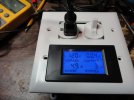
and this box I made to monitor power less than $10
DSC06629.JPG
I know it seems excessive
 
Hahahaha, thanks for the warning! but what about touching the top metal plate while ON? I guess that if the ground is connected OK, then it should be safe, right?

One of the best pieces of safety advice I've been given regarding testing tube amps with a meter is to tie one hand behind your back. Set the ground with one hand, then use the same hand to probe. I use a grabber on the ground so it won't move.

There are times i literally have to sit on one hand up keep it from trying to get involved.
 
Is there any particular brand or model of Variac that you would recommend? and how many amperes or watts would I need to be safe? Also, how do you handle ground with the Variac?
Is there no chance you would want to do this as a DIY project? The bucking transformer as described at Elliot Sound is the most appropriate for hi-fi, because the series current to the amplifier only passes through the high current secondary winding. It would be worth your time to read the theory he presents on this, if you haven't already. I'm in the process of building one now to reduce the line voltage to my older tube gear. Line voltage here sometimes exceeds 125V, and when that happens, the filter caps in units like my old Citation V are operating very near their maximum voltage rating.

To get this done, I bought a transformer with a 115/230 primary and a 10/20V secondary. It's a Signal (BEL) transformer model A41-175-20, currently available new from sources like Digikey for less than $35. This combination of input and output voltages allows using the transformer to reduce line voltage by (approximately) 5V or 10V (17A max current) or 20V (8.5A max current) when operated on a 120V line. I'm installing mine in a Hammond 1550F cast aluminum enclosure along with a couple standard 3-wire outlets and a fuse. I plan to simply hardwire it for a ~5V drop. Just food for thought.

Screen Shot 2024-07-27 at 10.02.15 AM.png

Jack
 
Is there any particular brand or model of Variac that you would recommend? and how many amperes or watts would I need to be safe? Also, how do you handle ground with the Variac?

Thanks!

Far from an expert, but vevor sells a 20a variac with 2 grounded outlets and a meter for not too much. For one that's getting set and forgotten there's no need to get fancy. I have one of theirs with an analog meter that works just fine. You cannot trust the labels on the dial though, expect it to be an estimate as it will vary with line voltage and whomever put the sticker on. Use a voltmeter to set it. It works just as well as my others, but unlike many older ones it has that ground plug. Some old ones don't have polarized sockets.

Or you could plop down a couple hundred for a new staco, or less for a used one.
 
Far from an expert, but vevor sells a 20a variac with 2 grounded outlets and a meter for not too much. For one that's getting set and forgotten there's no need to get fancy. I have one of theirs with an analog meter that works just fine. You cannot trust the labels on the dial though, expect it to be an estimate as it will vary with line voltage and whomever put the sticker on. Use a voltmeter to set it. It works just as well as my others, but unlike many older ones it has that ground plug. Some old ones don't have polarized sockets.

Or you could plop down a couple hundred for a new staco, or less for a used one.
@loudnoises Thanks for the head up, this one, right? Even though it is 15 amp, which is 1500 watts at 100 volts, that should be more then enough for my amplifier even when using 300Bs.

300B pulls more watts than 45 or 2A3. So, it is good to calculate with 300B for safety. From a very general perspective, Two 300B may pull 120 to 200 watts, four 717As pull around 20 watts, two 83s pull around 20 watts.

Roughly, that is a total of: 240 watts plus another 100 watts for capacitors and transformer, for a total of 340 watts for both channels. Lets call it 400 watts to be safe. That is 200 watts per channel since in this amplifier each channel has its own IEC and power transformer. So, to be on the safe side, I would need 400watts transformer per channel. So, total would be 800 watts. The 15 amp Vevor providing 1500 watts is enough. And, on top of that, I like much better the sound of the 2A3 and 45 than the 300B. So, the watts requirement will go even lower.

I have a polarity tester that has a display that shows voltage so I can use it to check the exact voltage coming out of the Vevor Variac.

I actually received the UMI Amazon voltage converter and it does not look reliable. I wanted to open it to see how is the ground connected but if I do it and return it, Amazon may not take it. Also, the Variac may be a better investment if I keep in the DIY path. Even if I upgrade to a better transformer, the Variac will be useful. Surely, the Variac does not rate high in the WAF factor (but I can hide it behind the subwoofer!). So, Im returning the UMI.
 
Last edited:
Back
Top Bottom