• The move to the new server is done. There are some software and database maintenance updates in process. This has us passing the hat around to help out. We appreciate any donations. Seriously, even a dollar helps. The payment page may be found here - https://www.audiokarma.org/support.html

Help with ground in a SET amplifier from Japan

Is there no chance you would want to do this as a DIY project? The bucking transformer as described at Elliot Sound is the most appropriate for hi-fi, because the series current to the amplifier only passes through the high current secondary winding. It would be worth your time to read the theory he presents on this, if you haven't already. I'm in the process of building one now to reduce the line voltage to my older tube gear. Line voltage here sometimes exceeds 125V, and when that happens, the filter caps in units like my old Citation V are operating very near their maximum voltage rating.

To get this done, I bought a transformer with a 115/230 primary and a 10/20V secondary. It's a Signal (BEL) transformer model A41-175-20, currently available new from sources like Digikey for less than $35. This combination of input and output voltages allows using the transformer to reduce line voltage by (approximately) 5V or 10V (17A max current) or 20V (8.5A max current) when operated on a 120V line. I'm installing mine in a Hammond 1550F cast aluminum enclosure along with a couple standard 3-wire outlets and a fuse. I plan to simply hardwire it for a ~5V drop. Just food for thought.

View attachment 3261357

Jack

Thanks for the details! I think that this is clearly the best path. But, I may go with a Variac now, since it will be a faster solution to start tuning the sound of the system that has new speakers and new amplifiers. While I start tuning the sound, moving speakers and deciding if I need the subwoofer or the Mini DSP, I can do this DIY project.

Surely, this bucking transformer box will have a higher WAF than the Variac. My system is in my living room, not in a dedicated room, so WAF plays a big role.

If I do this, I would prefer to keep the power transformer of the SET amplifier in the 100V tap as it is now, mainly to avoid having to check the operating points for all the tubes. In that case, I would need to bring down 120 -122v (I measured it yesterday at my wall outlet with a polarity tester with voltage meter) to 100V, that is almost 26%, I guess I would need a bigger transformer for that, but, how would I know what transformer to choose to get that reduction? is there a formula I can use regarding primary and secondary windings to get a given reduction?
 
One of the best pieces of safety advice I've been given regarding testing tube amps with a meter is to tie one hand behind your back. Set the ground with one hand, then use the same hand to probe. I use a grabber on the ground so it won't move.

There are times i literally have to sit on one hand up keep it from trying to get involved.
This may have to be my main technique for a loooong time!

Even meditating most mornings, I have mostly high energy all day long. So, I may need to tie my arm behind my back to protect myself while doing this
 
Last edited:
One can go overboard with electrical test equipment

I use a cheap simple small 3A red one, like this one from parts express

and this box I made to monitor power less than $10
View attachment 3261296
I know it seems excessive
@Omegaman Do you start your amplifier and variac normally? or you do a sort of soft start manually with the variac?
 
No, you'll still need to drop the voltage. About the hot/neutral thing, one way to check is to use your voltmeter to test the AC wall outlet. One of the slots will measure 120VAC to the ground prong. That's the hot wire. The other slot should measure 0V. That's neutral. Once the step down transformer is connected to the wall, you should measure the same relationship at its IEC outlet. The only difference is that the ground connection is a slot rather than a round socket. This will confirm that everything from the wall to the output of the step down transformer is OK. We have to assume the AC cable plugged into the transformer is also OK, so the only thing left is the wiring inside the amplifier. It might be a little tricky without a schematic, but generally speaking, there shoujld be a wire connected to the hot terminal of the IEC connected directly to a fuse holder. From there, it should travel to the power switch and anything that's supposed to be powered all the time, like a microprocessor or remote control board. In your amp, the IEC is integrated with the fuse holder and power switch. Once you know which input pin of the IEC is hot, it should be possible to determine the rest with an ohmmeter. I know it's a bit of trouble opening the amp for this, but I think it's worth doing.

Jack
@TriodeLuvr I hope you are well.

I opened the amplifier, took some photos, and inspected the cables coming out from the fused IEC power switch.

My Variac is arriving in 4 days or so. So, I have not been able to take voltages inside. But, photos are already telling a story.

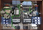
If you look at the complete photo of the amplifier, below. That shows in green the ground path coming out from the fused IEC power switch. I know that prong is ground because I found a wiring diagram for that power switch online. In that photo you can see that the green line carrying ground meets another two lines in a first stop (Number 1 in the picture) and gets attached to the plate of the amp, and then it goes to stop 2. (Number 2 in the photo). So, i think that ground is OK in the amplifier, right?

Now, for polarity it is more complex I believe.

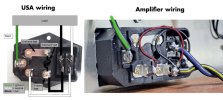
If you look at the other picture attached, on the left side it is the correct wiring for USA polarity for the fused IEC power switch, and on the right side is the wiring I found inside the amplifier. I am copying below a text from the wiring instructions I found:

¨Power connects to the front, and the exposed electrodes are on the back. A fuse connects the "unfused hot" to the "fused hot" section on the back (see image). The fuse is internal to the enclosure and can be accessed from the front.To incorporate the switch into the circuit, two jumpers need to connect the left-most electrodes to the switch. Notice that the switch has two sets of electrodes, the narrower set and the wider set. The jumpers should connect the socket electrodes to the narrow set in order for the LED in the switch to work. Polarity shouldn't matter. Wires connected to the wide set of electrodes, in addition to the ground, continue on to your load.¨

So, the in the amplifier wiring, the jumpers are there connected to the narrow set of sockets, but with different polarity, although according to the instructions that should not matter. The load goes to the wider set of sockets on the right side. I have painted the cables that could be hot or neutral with colors, hot is either the blue or the yellow cable. Nevertheless, the weird thing is that there is no cable connected to the most right socket of the wider pair of sockets.

Any help is greatly welcome!

Thanks,

Alan
 

Attachments

  • Ground 1.jpg
    Ground 1.jpg
    163.5 KB · Views: 13
  • Polarity in IEC.jpg
    Polarity in IEC.jpg
    72.8 KB · Views: 10
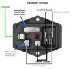
I made an easier to understand diagram of the correct wiring of a IEC 3 prong fused power switch and the way is connected in these Japanese amplifier.

I am trying to get my head around this wiring.

If I understand correctly, AC is alternating current so polarity only matters in terms of cutting/stopping/opening the live wire connection when a power switch is in the OFF position. That way, when the power switch is in the OFF, there is no live current passing through the device, right?

Then, after AC goes through the power switch and into the amplifier, polarity does not matter since the power transformer does not see polarity, is that correct?

Now, if all that is correct, then I just need to wire the fused power switch in the correct way for the USA wiring, see below.

Correct Wiring.jpg

You can see below a clear diagram of how the Japan amplifier fused power switch is wired.

Amp Wiring.jpg

The fact that the jumpers for hot and neutral coming from the IEC do not go to the same positions (as per the correct wiring) on the switch side would only matter if this switch when OFF only cuts the live/hot wire connection, right? If the power switch actually cuts both, neutral and hot, when OFF then it does not matter where the jumpers go on the right side, as long as both go on the narrow (lower) pair of electrodes, is that correct?

Taking into account that it is the live/hot wire that should always be fused, then I guess that the yellow cable is live/hot?

But, why the cable in yellow is connected to the fused live/hot? sort of bypassing the power switch?

Thanks,

Alan
 
Polarity could matter if the transformer is wired with a CT that's being used.

The hot is always fused at first so that under all circumstances a short will take it out. Switch off, or failed open even.

I'm trying to understand your issue here. If the yellow cable is feeding voltage always I would suspect some sort of auto on sensing or volatile memory. Neither of which I expect this tube amp has...
Yes, you are right in thinking that this amplifier does not have auto sensing. No way it has that.

Unless it is the red cable that is live/hot and it is simply going to the wrong male IEC prong (on the left) because Japan current is mostly not polarized?
 
Back
Top Bottom