• The move to the new server is done. There are some software and database maintenance updates in process. This has us passing the hat around to help out. We appreciate any donations. Seriously, even a dollar helps. The payment page may be found here - https://www.audiokarma.org/support.html

Help with HH Scott 208 (later model)

jonkelley

New Member
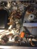
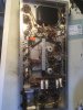
Hi all! I recently purchased a HH scott 208 with out any tubes. I plan on cleaning and recapping to get it back in working order. Upon closer inspection i came across some odd things.

1. two 1/4 in. jacks (one mono and one stereo) were added to the audio inputs. My thought was that the previous owner was trying to mod it into a guitar amp.

2. All of the leads in the chassis are painted black. Perhaps shield blocking paint?

3. The power cord was cut and the plug was replaced with ring terminals.

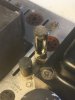
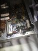
4. One of the chassis mount resistors is destroyed (I was aware of this when purchasing.) Can anyone confirm this resistors value?

5. A capacitor has been replaced with an orange 100/63. What value should this cap be? I found a picture of a re-capped amp with this cap showing 47/160.

Another thing with the destroyed resistor. The ceramic radial can resistor used is almost impossible to find. I've read that these resistors get very hot, which is why they are mounted on top of the chassis. If I replace it with a modern resistor under the chassis will it get to hot and potentially cause damage? My concern with installing a chassis mount resistor is that the ones I've found are axial and would have very high voltages present.

Why was the resistor destroyed? I cant tell if it burned or was smashed. If it burned, why? should i check the transformer voltages?

I'm excited about this project and am looking forward to getting this amp up and running. Any thoughts or insight would be greatly appreciated, thanks in advance!
 

Attachments

  • IMG-2669.JPG
    IMG-2669.JPG
    73.5 KB · Views: 65
  • IMG-2664.JPG
    IMG-2664.JPG
    125.4 KB · Views: 62
  • IMG-2667.JPG
    IMG-2667.JPG
    77.5 KB · Views: 61
  • IMG-2665.JPG
    IMG-2665.JPG
    113 KB · Views: 62
  • IMG-2662.JPG
    IMG-2662.JPG
    99.9 KB · Views: 61
Register to hide this ad
It looks like some rufus did try and make s guitar amp.
Luckily they didn't screw up too much from the looks of it.
Since they drilled the chassis I would opt to mount the big resistors inside, using the Dale resistors which have mounting tabs, and use heat sink compound to help move the heat to the chassis. I'll look at mine to confirm the value.
You want to talk to Jim Mcshane for power tubes, and get the 7591 tung sol. He'll have you rework the bias supply in order to run them, but they are the best available to us at the present time.

You shouldn't have any trouble replacing the power cord. That's pretty standard. Couldn't give you the reason behind the painted leads.

The cooked resistor (boy that sucker is really cooked) is probably for the screens supply.

Should be a straight forward project.
Check to see what your B+ runs at. Dave has one which runs with way too much B+, and special attention was required. They are pretty awesome little power amps when working right, and attractive to boot.
Congratulations.

IMG_20210209_102247_028.jpg
 
Above chassis resistors on mine are 15k, (taller) and 2k(shorter of the two)
I would think those values would be commonly available still, although high wattage resistors do cost a bit more than their 1/2 watt counterparts.

I installed 1 ohm, or 10 ohm cathode resistors (memory isnt the best) in mine for checking the bias, and ended up swapping around some resistors to get the bias supply to run the tubes at a bit under maximum. The stock design runs the snot out of them and that just seems reckless and wasteful to me.
Jim Mcshane will likely also direct you to lower the bias current otherwise he might not sell you the tubes. I've got a pretty comprehensive performance overview written up on mine, because I had it listed for sale. I definitely wouldn't try and quote that from memory...

When a buyer came go look at it, it committed suicide on the spot. Her way of telling me she wants to remain in my possession. These things have a mind of their own sometimes, and if this one wants to stay here, I guess I cant really argue.
 
Above chassis resistors on mine are 15k, (taller) and 2k(shorter of the two)
I would think those values would be commonly available still, although high wattage resistors do cost a bit more than their 1/2 watt counterparts.

I installed 1 ohm, or 10 ohm cathode resistors (memory isnt the best) in mine for checking the bias, and ended up swapping around some resistors to get the bias supply to run the tubes at a bit under maximum. The stock design runs the snot out of them and that just seems reckless and wasteful to me.
Jim Mcshane will likely also direct you to lower the bias current otherwise he might not sell you the tubes. I've got a pretty comprehensive performance overview written up on mine, because I had it listed for sale. I definitely wouldn't try and quote that from memory...

When a buyer came go look at it, it committed suicide on the spot. Her way of telling me she wants to remain in my possession. These things have a mind of their own sometimes, and if this one wants to stay here, I guess I cant really argue.

Thanks for the advice! I think we may have different version of the amp. Mine has only 2 can capacitors as opposed to the usual 3. There are also 2 bias adjust pots as well as a test point on the chassis.

I cannot find a schematic for this version. The burnt resistor is connected to the rectifier tube. I believe it would be R210 (80 ohms 10w) on the available 208 schematic. Before i replace the resistor Id like to confirm the value on the version of amp i have.
 
jonkelley,
Welcome to AK! 208 is a nifty amp--good luck with it. I like trainbuftony's idea for the chassis-mounted power resistor underneath. That would keep a bunch of heat out of the bottom space where it stresses components (that's why the chalk stick resistors are on top). If your bad resistor is 80 ohms 10W, I found a way to replace one on my Scott 272 with a modern top-mount 'cement' wire wound resistor, albeit a rectangular cross-section stick instead of round. You can see what I did in this thread if it's helpful:

https://audiokarma.org/forums/index.php?threads/my-very-own-scott-272.915784/

Check post #4 "Replacing the Chalk Stick Resistor".

Dave
 
I liked my HH Scott enough that I decided that building a clone would be fun.
(Actually it didn't start out that way)
I used what I had and put together this neat little clone which makes a great sounding 20 watts per channel. I used Stancor opts, and a organ power transformer.
If found a forever home with a friend of a friend.
I literally built it with spare parts.
I guess there's really no point to this post, besides to say that the little 208 has made a favorable impression on me.
If I had to choose between the 208 and a ST70, the 208 would get my vote 7 days a week. They look better, sound better, and can often be had cheaper, and the power output difference is negligible.
Such a sweet little amp.
 

Attachments

  • 20200213_190021.jpg
    20200213_190021.jpg
    59.8 KB · Views: 24
Hmmmm. I have a spare set of Heathkit (Stancor) AA-100 output transformers and a Hammond PT lying around. I used another set of AA-100 iron to make Dave Gillespie's SA-100 clone (which is my go-to power amp with my revived Fisher 400CX2 pre at this point). I wonder if I should try a clone of the 208 as well? (apologies to OP for the diversion....)
 
Upon closer inspection of the photos the resistor that has a glob burned out of it is right off the rectifier B+ supply, before the first cap. The first cap off the rectifier always takes the hardest beating, and shorts first most of the time in my experience. It would not be unusual to have that cap short, and draw sufficient current to cook the guts right out of the only thing between the power supply and ground which can dissipate heat until that device goes open.
Common failure and a result of running the amp on dead 60 year old caps.
Got any chokes laying around?
This would be an ideal place for one.
Someone has already prevented a 100% restoration when they drilled it, so in my opinion, it would not hurt originality to put a choke there because it cant really be restored to 100% original. The choke is a great device for creating low impedance power supplies, with low noise, and the reason Scott didn't use one was the cost.
So you get to have a little more fun with it and make it the best amp it can be!
 
Last edited:
Thanks guys!
Very useful forum Dave. I was looking at resistors similar to that but was having difficulty finding one with the correct wattage. I like Train's idea of adding a choke, i might do some more research in that direction. I dont really care about keeping the amp original as its been drilled and alot of the artwork has come off. Going for function over form on this one.

Dave, I saw that you used Hayseed caps. I was going to use parts express caps to cut down on cost but the Hayseeds look really nice. Do you think its worth the approximate $20 difference per cap?

Also, when i said that the orange 100/63 cap was coming off of the rectifier tube i was wrong. Its attached to the negative dc bias and is grounded on the rectifier tube socket.

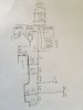
Attached is my attempt at a schematic, apologies for the chickenscratch! On that note do you have any recommendations for free schematic drawing software?
 

Attachments

  • IMG_2671.JPG
    IMG_2671.JPG
    58.5 KB · Views: 14
Lol software.
I use graph paper and a ruler, to make the lines straight and I have a stencil called a "Gibson radio rule" which has all the symbols for drawing tube schematics. They look sharp as a tack, and you wont be SOL in 10 years when your new computer can't read your old files.

When you sell it. Give them a Xerox of your work and keep the blueprint for yourself.
That way you have a blueprint for success next time that amp (or another like it) crosses your bench.
 
Jon -- I also welcome you to AK! A couple of comments you might find useful:

1. The original cap after the 4.7K in the bias supply was a 50 uF @ 75 vdc.
2. The resistor coming off the rectifier tube is a 20Ω resistor -- use a device of 20 watt rating to replace it.
3. The original bias diode was a half wave selenium rectifier -- not a bridge diode like you show. If your unit in fact has a bridge installed, it was no doubt installed by a previous owner.
4. The 47K resistor you show connected between the bottom of the third 30 uF cap and ground is not shown correctly. That cap, being within the same can cap as the 4th 30 uF cap is in fact grounded by virtue of being in the same can. The 47K resistor should be shown as connected across (i.e., between) the + and - (i.e., ground) terminals of the 4th 30 uF cap. The positive terminal of the 4th 30 uF cap is the supply source for the pentode stage of the driver tubes.
5. The late version 208 is quite similar to the power amp section of the 299D, which can be used for general reference, but is not of course exact. Short of finding a true late model Scott schematic for the amplifier however, it's much better than nothing.

My own unit was originally producing 545(!) vdc at the output of the rectifier, and in fact did require quite the shenanigans to bring it down as Train mentioned, in a manner that still allowed it to produce full power in both channels with low distortion. The thread on my own unit can be found here, which might be helpful if only to say the the work is well worth it. It's an early model that (among other things) I added Bias controls to.

https://audiokarma.org/forums/index.php?threads/taming-the-hh-scott-208.792617/

Good luck with yours!!

Dave
 
Last edited:
I like the Hayseed Hamfest cap sets and find that they aren't much different in cost than if I bought, say, CE brand cans (which also might not be exactly the desired value due to selection) and they drop in very easily. I hear they're running a little behind these days, but I often go with their sets and have had them make up custom sets when they don't have a stocked set (example: the 272).
 
Jon -- I also welcome you to AK! A couple of comments you might find useful:

1. The original cap after the 4.7K in the bias supply was a 50 uF @ 75 vdc.
2. The resistor coming off the rectifier tube is a 20Ω resistor -- use a device of 20 watt rating to replace it.
3. The original bias diode was a half wave selenium rectifier -- not a bridge diode like you show. If your unit in fact has a bridge installed, it was no doubt installed by a previous owner.
4. The 47K resistor you show connected between the bottom of the third 30 uF cap and ground is not shown correctly. That cap, being within the same can cap as the 4th 30 uF cap is in fact grounded by virtue of being in the same can. The 47K resistor should be shown as connected across (i.e., between) the + and - (i.e., ground) terminals of the 4th 30 uF cap. The positive terminal of the 4th 30 uF cap is the supply source for the pentode stage of the driver tubes.
5. The late version 208 is quite similar to the power amp section of the 299D, which can be used for general reference, but is not of course exact. Short of finding a true late model Scott schematic for the amplifier however, it's much better than nothing.

My own unit was originally producing 545(!) vdc at the output of the rectifier, and in fact did require quite the shenanigans to bring it down as Train mentioned, in a manner that still allowed it to produce full power in both channels with low distortion. The thread on my own unit can be found here, which might be helpful if only to say the the work is well worth it. It's an early model that (among other things) I added Bias controls to.

https://audiokarma.org/forums/index.php?threads/taming-the-hh-scott-208.792617/

Good luck with yours!!

Dave

Very useful info, thanks! I also really appreciate your help setting the schematic straight!
Hopefully i will be able to test the power transformer this weekend and get specifics on voltages.
 
I also have a late Scott 208, with the same 20 ohm Standee resistor broken.
As the script on the Standee was long gone when I got it, and there being no schematic for these late units, I am delighted that Dave G has clarified that resistor's value(s). Many thanks Dave!
That said, I have searched Mouser, Digi-Key, Newark, and so on, in vain, for a 20 ohm (and 22 ohm) 20 watt (or 25W or 30W) wirewound ceramic cement resistor, through hole, radial, yada-yada, of the type that Dave451 used in his Scott 272 restoration.
So far the well is dry.
If anyone happens to know of a source for that type and style of resistor, in any of those value combinations, I will certainly appreciate the assist in locating one.
Thanks!
 
I also recently purchased a later HH Scott 208.

I'm glad I saw your thread, mine is completely missing any kind of resistor where the 20 ohm one is squpposed to be. I saw the hole and wondered if I was missing something.

I'm going with Hayseed for the 2 cans. With only 2 capacitors in them it wouldn't be a big deal to re-stuff them, but its just so much easier and cleaner to get them from Hayseed. They are pretty far behind though, so if you're in a hurry you might want look elsewhere.

Mine has this weird white thing on top which I assume is for testing the bias. I haven't gotten that far yet. The guitar guy probably chucked yours in the garbage.

If you want to replace that bridge rectifier I asked the experts what to use in this post:

https://audiokarma.org/forums/index.php?threads/hh-scott-208-rebuild-question.953649/#post-14642232
 

Attachments

  • 20210321_201142.jpg
    20210321_201142.jpg
    96.8 KB · Views: 19
  • 20210321_201105.jpg
    20210321_201105.jpg
    179.3 KB · Views: 19
I also recently purchased a later HH Scott 208.

I'm glad I saw your thread, mine is completely missing any kind of resistor where the 20 ohm one is squpposed to be. I saw the hole and wondered if I was missing something.

I'm going with Hayseed for the 2 cans. With only 2 capacitors in them it wouldn't be a big deal to re-stuff them, but its just so much easier and cleaner to get them from Hayseed. They are pretty far behind though, so if you're in a hurry you might want look elsewhere.

Mine has this weird white thing on top which I assume is for testing the bias. I haven't gotten that far yet. The guitar guy probably chucked yours in the garbage.

If you want to replace that bridge rectifier I asked the experts what to use in this post:

https://audiokarma.org/forums/index.php?threads/hh-scott-208-rebuild-question.953649/#post-14642232
That funny white thing looks like it might be your missing 20 ohm resistor.
It looks like it's only got two wires going to it.
I'd try putting an ohm meter on each end and see what you get.
 
Oh yeah, good point Pablo.

110 ohm across the white thing. I'm pretty sure I saw another 208 with this on audiokarma but of course now I can't find it. Maybe Dave G will check back in to this thread...
 
If this were mine I'd replace that white, board thing with something substantially cleaner looking. Like perhaps a pair of chassis mount Dale power resistors in the gold anodized aluminum extrusion package...
I've mounted them to interior chassis walls and with a bit of heat sink compound they stay as cool as you could possibly expect them to..
 
If the top side replacement resistor measures 110 Ohms on your later version 208 then likely whomever did that work was using an early version schematic to work from as the early version units used an 80 Ohm resistor in that position. With the heat stress that resistor shows, it may have started out as an 80 Ohm piece, but most likely it is a 100 Ohm resistor that was deemed to be close enough to the intended -- although incorrect for the version -- value.

Dave
 
Thanks for clarifying that for me Dave.

I think I will follow trainbuftony's advice and mount a gold aluminum Vishay Dale 20 ohm resistor inside the chassis. The side of this plate in the middle looks like a good spot.
 

Attachments

  • 20210321_211738.jpg
    20210321_211738.jpg
    179 KB · Views: 15
Back
Top Bottom