The lack of service response from the seller notwithstanding, I'll second the vta board. Readily available tubes and Bob Latinos design make for a reliable combo. Pretty solid instructions as well.



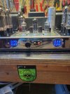
I did the same with mine. I also got rid of the 5AR4 rectifier and use a WZ-34 SS rectifier that mimics the voltage from of the 5AR4. The picrure below is before I installed the WZ-34.I'm a fan of those "three 12AU7 boards" as service replacements. Easy to source tubes, each output tube has it's own bias pot and I personally think they sound and look nice. For a non-techy end user, those digital bias displays that replace the octal sockets make a lot of sense too. On this one I added a volume control to eliminate the need for a pre-amp as well.
View attachment 3784472

Love those digital displays, I need to get a pair for mine.I did the same with mine. I also got rid of the 5AR4 rectifier and use a WZ-34 SS rectifier that mimics the voltage from of the 5AR4. The picrure below is before I installed the WZ-34.

Dynakit sells bias trimmers built into a pair of sockets for the front.Mine would like a set, but then I'd have to re-home the bias pots that currently live there. No idea where to put them, which is why they are there now. I suppose maybe I could swap the existing test points out for 4 of the small chassis mount pots I like to use, but then I'd have to re-design the bias/balance system I have now for individual pots.
They are a little bright. It doesn't bother me, but some have added #35 car window tint to put on the front of the plexiglass. You can find scraps at any place that does car window tinting. The meter kits don't come with diodes, so they can flicker a bit. Again, it isn't enough to bother me. I don't sit there staring at them while listening to music.Love those digital displays, I need to get a pair for mine.
Dynakit sells bias trimmers built into a pair of sockets for the front.
There is an adjustment screw in the keyway hole in the center.
You could put in one meter and a rotary switch to swap between tubes. Much less real estate.mine is using a pair of concentric pots in place of the front sockets, front knob is bias, rear is balance. If I put a pair of meters in the front sockets those pots lose their home. I can't put pots in the original rear location, holes are way oversized and the cap board lives under there now. About the only place I think they might be able to live is where the pin jacks now live near each tube for setting the bias. With 4 displays and a pot next to each tube it just seems to make more sense to have it be individual bias rather than bias/balance.
still would need to do something with the pots, and then there is a switch to find a home for.You could put in one meter and a rotary switch to swap between tubes. Much less real estate.
I own cars with zero instrumentation that are an "ignorance is bliss" situation but I can't quite bring myself to do that with my amps.Could install an auto bias board and lose the pots and the meters.
Rogue does something similar. One bias meter and four switches under a small plate up top. There are two thumb screws holding the plate in place.You could put in one meter and a rotary switch to swap between tubes. Much less real estate.
The muzishare X& does this as well, but I believe it uses 2 meters. They display VU but can be switched to tube 1 and 2 bias on that channel.Rogue does something similar. One bias meter and four switches under a small plate up top. There are two thumb screws holding the plate in place.

I check the dipstick every now and then, or as needed if something seems off.I own cars with zero instrumentation that are an "ignorance is bliss" situation but I can't quite bring myself to do that with my amps.
Yeah I own a 2012 Honda civic that didn't have a temp gauge and I had to add one to itI own cars with zero instrumentation that are an "ignorance is bliss" situation but I can't quite bring myself to do that with my amps.


I've installed these and like them a lot.Dynakit sells bias trimmers built into a pair of sockets for the front.
There is an adjustment screw in the keyway hole in the center.