• The move to the new server is done. There are some software and database maintenance updates in process. This has us passing the hat around to help out. We appreciate any donations. Seriously, even a dollar helps. The payment page may be found here - https://www.audiokarma.org/support.html

Help with repairing a SAE 2600

marmas

New Member
It is a very recent version (I think 1980), it has the toroidal transformer, 2 rectifier bridges and the modification on the protection board to eliminate the delay on the relay when switching off)

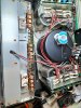
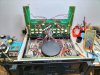
The flaw is that by setting the input sensitivity to -3 and 0 dB on any of the 2 channels you can hear a loud buzz in the speakers, the vu meters go beyond half scale and the final transistors heat up a lot.
By measuring the DC output it rises to 100/120 mV.
With the input sensitivity of - 12 or - 6 dB it works great and there is no abnormal heating.
The amplifier has all original toshiba transistors and the drivers are plastic, everything looks original, never been repaired.
The amplifier is set to 240V and feeding it to 220V (standard voltage in Italy) the power supply supplies approx. + 80 / -80V.
Connecting the input signal on one channel at a time everything works fine

I saw from the wiring diagram that the power supply should deliver +/- 105 V, do you think this could be the cause of the problem or do you have any idea what could be the cause of the failure?

Unfortunately I did not find the service manual on the net but only a wiring diagram, can you help me?
Many thanks to those who want to help me.
Massimo
 

Attachments

  • IMG20220505122935.jpg
    IMG20220505122935.jpg
    133.1 KB · Views: 60
  • IMG20220505163123.jpg
    IMG20220505163123.jpg
    151.1 KB · Views: 60
Register to hide this ad
The flaw is that by setting the input sensitivity to -3 and 0 dB on any of the 2 channels you can hear a loud buzz in the speakers, the vu meters go beyond half scale and the final transistors heat up a lot.

Buongiorno and welcome to AK. I think your amplifier is breaking into oscillation at these sensitivity settings. Do you have an oscilloscope that you could use to check for oscillation?

If you find that the amp is oscillating, I think it will be difficult for anyone to help with a precise diagnosis, but one likely suspect would be the power supply decoupling capacitor for the input stage, C5.

I don't know what to think about the low power supply voltages. If the main power filter capacitors were severely degraded, it might explain that. In that case there would be large "ripple" voltages (120Hz AC voltage superimposed on the DC power supplies), which you could also check with an oscilloscope.

I don't know a source for a full service manual. There are AK members who know more than me about SAE, so someone else may have a source.

Edit: the italics that follow are incorrect. See Racingh11's post later on for the correct info.

By the way, I notice that the schematic has "QUIESCENT CURRENT ADJ" labelled for R22. This is clearly an error. R22 actually adjusts DC offset, so it is to be adjusted for 0V DC at the amplifier outputs. Quiescent current (also known as idle current, or bias) is adjusted by R52. The schematic mentions a quiescent current of 30mA, but it is not clear how to make that measurement. I would suggest cleaning or replacing the R52 trimmer resistors - if they suffer from poor contacts, it will cause quiescent current to be very large, and likely damage the amp.
 
Last edited:
The Sensitivity/Gain switches change the feedback, more feedback less sensitive and vice versa. If your Sensitivity switches are dirty OR the resistors on the switch board are bad you may not have any feedback in those positions. If there is no feedback the amp will go nuts.

Craig
 
Interesting that the white and red wires from the meters to the board are opposite that of a 2500 I’ve got to finish yet. Just a curious thing is all, doesn’t matter as there hooked up the same.
 
Buongiorno and welcome to AK. I think your amplifier is breaking into oscillation at these sensitivity settings. Do you have an oscilloscope that you could use to check for oscillation?

If you find that the amp is oscillating, I think it will be difficult for anyone to help with a precise diagnosis, but one likely suspect would be the power supply decoupling capacitor for the input stage, C5.

I don't know what to think about the low power supply voltages. If the main power filter capacitors were severely degraded, it might explain that. In that case there would be large "ripple" voltages (120Hz AC voltage superimposed on the DC power supplies), which you could also check with an oscilloscope.

I don't know a source for a full service manual. There are AK members who know more than me about SAE, so someone else may have a source.

By the way, I notice that the schematic has "QUIESCENT CURRENT ADJ" labelled for R22. This is clearly an error. R22 actually adjusts DC offset, so it is to be adjusted for 0V DC at the amplifier outputs. Quiescent current (also known as idle current, or bias) is adjusted by R52. The schematic mentions a quiescent current of 30mA, but it is not clear how to make that measurement. I would suggest cleaning or replacing the R52 trimmer resistors - if they suffer from poor contacts, it will cause quiescent current to be very large, and likely damage the amp.

Thanks,
you mean the electrolytic capacitor C5 (100uf 50V) in parallel with the 51V zener diode?
Another thing that I do not explain is that the toroidal transformer only delivers 57 V (even without load) which, when rectified, give approx. 80 V, never 105 V! Could it be a version with a lower supply voltage? Or is it a fault in the transformer (does not heat up and does not hum)?
This wiring diagram with 2 rectifier bridges cannot be found !!
 
Does the amp act the same with no load connected? If your power supply gets loaded down to where the 51V Zener can't regulate it will cause a problem. Measure the voltage across the Zener while the problem is present. The ACV into the rectifiers should be approx. 80VAC in order to make 105VDC.

Craig
 
Thanks Craig,
I am wondering if the toroidal transformer can fail by lowering its voltage to 57 ACV on both outputs (as I said it does not heat and does not hum).
When I set the gain switch to 0 the DC supply voltage drops by approx. 10 V, the indicators go to full scale and the final transistors heat up a lot (self-oscillations?)
 
I’d verify the transformer if it were me. Disconnect all it’s outputs and make sure the input is at 220vac going in at its input wires then get a voltage reading at its outputs. That way you got power into it and what it’s putting out without anything “messing” with it.
 
I’d verify the transformer if it were me. Disconnect all it’s outputs and make sure the input is at 220vac going in at its input wires then get a voltage reading at its outputs. That way you got power into it and what it’s putting out without anything “messing” with it.

Without any load the transformer delivers 57-0-57 Volts, but they are too few to get 105 V DC .... Will the transformer be faulty or does this version of 2600 work at 80 V DC?
 
you mean the electrolytic capacitor C5 (100uf 50V) in parallel with the 51V zener diode?

Yes, that is what I meant. But I like llwtt's idea about the sensitivity switch, too.

Another idea occurs to me, but I have to say that I have not thought about it enough: If there was a poor connection between the center-tap of the power transformer and ground, could that explain the low secondary voltages, and perhaps also the (theorized) oscillations?
 
Without any load the transformer delivers 57-0-57 Volts, but they are too few to get 105 V DC .... Will the transformer be faulty or does this version of 2600 work at 80 V DC?

I don’t know if that version operates at different voltage or not. Never seen a schematic for that one. I think it’s unusual for a transformer to go bad though.
 
I was looking at some pics online of your version but they weren’t 220vac, only 100vac & 120vac versions. The 220 must have more wiring as it didn’t match up in the filter cap area.

I’m curious, where the ground wires are attached to the filter caps there is also a red wire attached with them. Where does that red wire go from each side?

Is this how you got the unit by the way or did it just go bad?
 
Tomorrow I will check and let you know how the transformer is connected. This is how the amplifier arrived and on the back it says: export model 240VAC
 
Here’s something interesting, the A501’s transformer operates at your voltages your getting.
 
About the A501, yes but this amplifier delivers only 250 W. I wonder how the 2600 with +80 / -80V does deliver 400W ?.......
 
By the way, I notice that the schematic has "QUIESCENT CURRENT ADJ" labelled for R22. This is clearly an error. R22 actually adjusts DC offset, so it is to be adjusted for 0V DC at the amplifier outputs. Quiescent current (also known as idle current, or bias) is adjusted by R52. The schematic mentions a quiescent current of 30mA, but it is not clear how to make that measurement. I would suggest cleaning or replacing the R52 trimmer resistors - if they suffer from poor contacts, it will cause quiescent current to be very large, and likely damage the amp.
R2 is for offset, R22 is for quiescent current of the VA stage, R52 is for bias current adjustment. Quiescent current is set by measuring voltage across each R23/24 and should be 1.86V for 30mA. The bias current adjustment is made by setting distortion to a certain level on the analyzer. Not sure what that is on this amp, I'm not an SAE expert, but the 2400L calls for .05 to .08% THD at 20khz, 1 watt. I like to have amps plugged in to a power usage meter when I set bias by the distortion method, just to make sure it is not using excessive power to accomplish it. Also can measure the current with the emitter resistors to be sure what it ends up at.
 
Last edited:
Back
Top Bottom