• The move to the new server is done. There are some software and database maintenance updates in process. This has us passing the hat around to help out. We appreciate any donations. Seriously, even a dollar helps. The payment page may be found here - https://www.audiokarma.org/support.html

Help with repairing a SAE 2600

About the A501, yes but this amplifier delivers only 250 W. I wonder how the 2600 with +80 / -80V does deliver 400W ?.......
Sounds like the amp is loaded, either it's oscillating or bias current is very high for whatever reason. +/-105V is unloaded voltage. +/-80V will get you 400W.

80V x .707 = 56.56VRMS

56.56^2 / 8 ohm = 400 watts
 
Could you try unhooking the amp modules from the power supply and seeing if it goes to the right voltages?
 
Could you try unhooking the amp modules from the power supply and seeing if it goes to the right voltages?
The power supply delivers +80 -80 V because the transformer delivers approx. 57 V AC. Self-oscillation is created when I place both sensitivity switches at 0dB, then the voltage drops to + 69 - 69V DC
 
Sounds like it went from low to lower. 69V won't get you 400 watts. From my understanding, it should be at +/-105V at idle and drop close to 80V at full 8 ohm load. If it's dropping below that, then it seems to be consuming a lot of power at less than an 8 ohm load.
 
I was looking at some pics online of your version but they weren’t 220vac, only 100vac & 120vac versions. The 220 must have more wiring as it didn’t match up in the filter cap area.

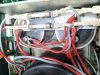
I’m curious, where the ground wires are attached to the filter caps there is also a red wire attached with them. Where does that red wire go from each side?

Is this how you got the unit by the way or did it just go bad?
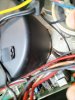
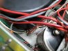
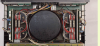
Here are some photos of the transformer connection:
IMG20220511112821.jpg IMG20220511113511.jpg IMG20220511113605.jpg IMG20220511113950.jpg IMG20220511114015.jpg
 
The power supply delivers +80 -80 V because the transformer delivers approx. 57 V AC. Self-oscillation is created when I place both sensitivity switches at 0dB, then the voltage drops to + 69 - 69V DC
This is with the fuses removed? Please try. You never know.
 
What’s the bias and QC readings ?
At the beginning you commented that with only one input hooked at a time it works fine, does that include setting at 0 & -3 DB ?
 
What’s the bias and QC readings ?
At the beginning you commented that with only one input hooked at a time it works fine, does that include setting at 0 & -3 DB ?
The power transistor bias is 2.1 V and the QC is 1.9 V ( on R23-24 62 ohm resistor)
Yes, one channel at a time it works fine also at 0dB.
 
R2 is for offset, R22 is for quiescent current of the VA stage, R52 is for bias current adjustment.

I stand corrected, and a bit red-faced. I was looking at a truncated window of the schematic, didn't even notice R2, and obviously didn't look closely enough at what R22 does. Thanks!
 
There are four capacitors which are for high frequency stability. My guess would be one of them is open - the more feedback, the more likely for stability to be a problem. The lower the gain, the higher the feedback. The caps are two 22 pF and two 47 pF. The schematic I have shows them as c7, c8, c10, c11.
 
There are four capacitors which are for high frequency stability. My guess would be one of them is open - the more feedback, the more likely for stability to be a problem. The lower the gain, the higher the feedback. The caps are two 22 pF and two 47 pF. The schematic I have shows them as c7, c8, c10, c11.
I will change them and let you know,
thank you,
Massimo
 
I had weird oscillations in a 2600 I was working on. Finally found that all the grounds in the amp go to the negative speaker terminals and they were loose.
 
I’ve had too many of those female spade terminals actually crack and you barely have a connection if your lucky without replacing.
 
There are four capacitors which are for high frequency stability. My guess would be one of them is open - the more feedback, the more likely for stability to be a problem. The lower the gain, the higher the feedback. The caps are two 22 pF and two 47 pF. The schematic I have shows them as c7, c8, c10, c11.
I have replaced these bypass capacitors along with all electrolytics (excluding the ones from the power supply) but no improvement !!
By applying the signal on the single channel everything works, together the auto oscillation starts ........
 
06656C19-E39A-4AFA-B946-C0351B5D67DF.png
In this pic there is a single black wire on the upper left and a black & brown on the upper right both sides going to the plate that connects the filter caps. You have a red wire that is also connected to each side. I’m curious where those two go? I find no other pictures showing that unless it’s something to do with 220vac incoming.
 
Back
Top Bottom