• The move to the new server is done. There are some software and database maintenance updates in process. This has us passing the hat around to help out. We appreciate any donations. Seriously, even a dollar helps. The payment page may be found here - https://www.audiokarma.org/support.html

Help with Technics SU-V505 amplifier (not starting)

Ok, back on track: all the transistors are in place and with the collectors of Q303 and Q304 to GND, I now get powerup. I can hear the relay closing and no smoke came out, also indicated by the series lightbulb which remained dim all throughout.

Measurements: the middle pins of the sense resistors, with respect to GND show around 66mV one one channel and around 90mV on the other. What shall I do next ? Replace Q303 and Q304 as well and go for it ? Some adjustments to those pots will need to be made for sure once we get there.
 
I’d try 2 3.9k resistors in series from collector to Emitter (Q303/304)

Install Q71/72

Power up, check dc offset

If all is well install Q303/304 - let warm up 15 mins

Adjust bias to spec,

Enjoy the music
 
I’d try 2 3.9k resistors in series from collector to Emitter (Q303/304)
So with the collectors of Q303 and Q304 still to GND via those 3.9k resistors I currently have in place, I also tie their emitters to GND via 2 3.9k resistors ? I say GND because the collector is already at GND, so the resistance between GND and emitter would be the 3.9k times 3 (the resistor that's already in place, plus the two extra you suggested). Is this right ?
 
Emitters of 303/304 are -V.

In operation output stage is pulled down to -V via 7.8K resistance

(No longer to ground)
 
Oh right, forgot it's a symmetrical supply. So 7.8k resistor between collector and V- (or emitter, same thing) with Q71 and Q72 in place ?
 
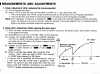
Another question while I'm waiting for some more transistors to arrive: how do you measure DC offset ? The manual talks about IcQ adjustment which I'm assuming is "bias" ?
 
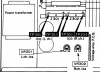
Dc offset is measured from centre pin of Emitter resistor to ground should be optimally 0mv 0-10mv is often seen

In this set there is no dc balance adjustment- AN7062 controls this.


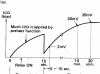
As for icq - see attached


B9F6D54A-A431-4123-A353-FD8BD3F25B81.png

744D0390-AA8E-4063-BFC8-99CF45FD4A1E.png
 
Ok, here's where we stand: collectors of Q303 and Q304 to the emitter pad via two 3.9Kohm resistors in series and Q71/72 installed: no startup again. When the time comes for the relay to normally close, I start to hear some faint squealing noises coming from the amp...can't say where they're coming from though. Nothing's smoking or doing funny stuff, but not turning on either. Q71 and Q72 are still fine. Is IC71 bad and would require replacing (I have two spare ones) or is it because I should've gone straight to V- with those two 3.9k resistors ? In the schematic, the emitter pad itself (where I made my connection) doesn't go straight to V- but rather through a 47 Ohm resistor.
 
Last edited:
Ok so Q303/304 are out (replaced by resistors) and Q71 / 72 are in

What are voltages at collectors of Q71 / Q303 and Centre pin of Z301.... then Q72 / Q304 and centre pin of Z302

Also what voltage is at emitters of Q303/304 should be -V level unless fusible resistor open circuit
 
Ok so Q303/304 are out (replaced by resistors) and Q71 / 72 are in
Correct, with the collector going to the emitter via those resistors I mentioned (which actually makes 3 of them because we're also counting R311 and R312 which I mentioned on those emitter pads).
I shall measure and report back. Thank you.
 
Emitters are at -39v.

Ok something just happened: I was measuring the collectors of Q303 and Q304 and the relay suddenly clicked and scared the sh!t out of me :)) However it didn't stay on: it just cycled rapidly on-off like there was a fault on there. Q304 (with that resistor arrangement) has around 30-33v on its collector. Q303 on the other hand was a bit different: it has -1v on its collector.
Z302 measures around 30v on its center
Z302 measures a couple of milivolts (around 200 though that could be zero and its just multimeter "noise")
Q71 starts off at -30 something volts which drops (or would that be increases?) to around 1.9-2 when the relay attempts to turn on and it just stays like this afterwards
Q72 is different: it cycles through -30 through 30v randomly and never settles - something wrong on this channel most likely.
 
Last edited:
Could be voltage amp

It’s definately hunting... check joints etc -

If collector of Q72 is all over the place, is this seen at Z302 centre pin

For interest- what voltage from collector Q71 to collector Q303 then check voltage at collector Q72 to collector Q304

These should be 3.6V - 4v
 
I just realised that I most likely didn't replace IC71 after the SECOND failed attempt (when I started talking about those diodes and how I tried removing one and sh!t started smoking), so that could be the issue all along. The timeline goes like this: I killed it once, ordered a second one, probably killed that as well with the diode business, then I ordered 2 more and they're still in the package so the one installed is likely faulty as well from the second time around but I forgot about it. I will however take the measurements you requested, but I believe I already did Q303/Q304 like you asked - just read a couple of posts above.
 
Back
Top Bottom