• The move to the new server is done. There are some software and database maintenance updates in process. This has us passing the hat around to help out. We appreciate any donations. Seriously, even a dollar helps. The payment page may be found here - https://www.audiokarma.org/support.html

Here It Is: The All Singing All Dancing HTMCPS

I moddified my volt meters as in the pictures below.
Got a design for my project case on the drawing board, but this will have to wait till I recover from an opperation on my tendon.
This takes place in a few days time with a lengthy recovery time, so I will be watching what everyone else is doing for a while.

:lurk:
 

Attachments

  • HTMCPS_006.jpg
    HTMCPS_006.jpg
    114.6 KB · Views: 45
Progress

Some bits were on back order for a month, but I finally got enough ingredients to start cooking. I went with Elna Silmic lytics, and 2.0uF Audiocap Thetas sans bypasses - thus the Dolly Parton look. :-) Finding a case to fit will be a shopping trip for later.

DollyPartonSmall.jpg


Being naive, and thinking this was a good idea, I chopped up an old Monster Cable RCA patch cord, seemed to be built for maximum shielding. But the cables are so stiff they broke the solder joints when flexed. So off to Radio Shack to find something more appropriate.

OctapooSmall.jpg


Now for a stupid question - no post of mine would be complete without it. To cap things off, will a single 12V lantern battery connected to the + and - terminals fire this up? I read about 9V, four 12V batteries, 24V... what's the deal?
 
Last edited:
Lantern batteries are 6V, so you'll need 4 of them to get 12V.

That's related to my question. I recently tried lantern batteries, and just hooked them up with alligator clip jumpers. The amount of noise, both hiss and radio interference, was alarming. (I live close to a big transmitter.) It never occurred to me I might need shielded wire for the batteries. Anybody else get this issue?
I haven't tried simply twisting the jumpers. Maybe that will help.

Otherwise it sounds great on regular 9V batteries.
 
Done - Almost, OK not quite

Round two on the leads - used twisted 18 gauge speaker wire that has a double sheath, what the heck.

HTMCPSDunSmall.jpg


Radio Shack came through on an 8xAA battery holder that attaches to a 9V battery lead. (We've got a ton of AA's in the house from the years when everything seemed to take them).

Here's a 12V lantern battery. Nice screw terminals, but huge - not everybody may be able to house or hide one:

http://www.ebay.com/itm/Rayovac-12V...t=US_Single_Use_Batteries&hash=item2a17381a78

Upon play back, I get a a micro second of sound, then cut out/silence. I used 1K ohm resistors for R2/10 per the calculator, but as Phillip predicted that may be too much. Going to swap in 660 Ohm next. Had to try the high gain first, as a constant, nagging problem of my Deonon DL-103D has been low output and an overworked amp.
 
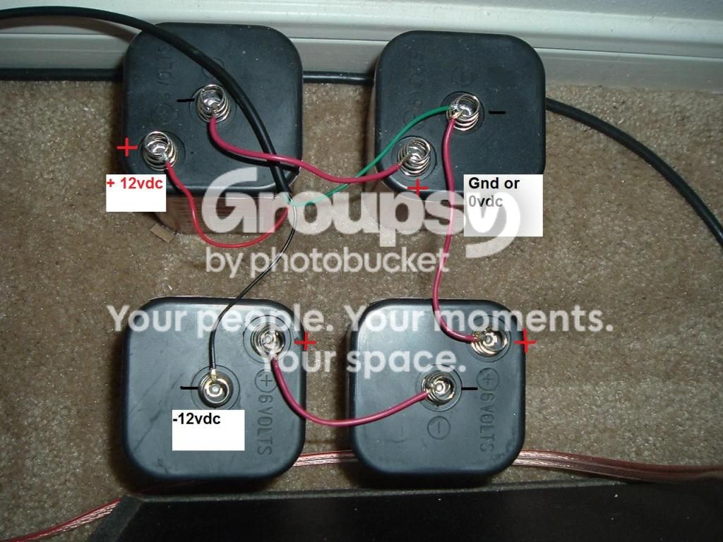
Here's how to connect up the 6v lantern batteries.

The Red wire is the Positive connection, the Green wire is the Ground and the Black wire is the Negative.

I get them from Walmart in the camping section, you can get twin pack Rayovac's for around $5.00 per pack.

Never connect the batteries without the center (0v) ground connection.

All mine are dead quiet.


LanternBatteries.jpg
 
Round two on the leads - used twisted 18 gauge speaker wire that has a double sheath, what the heck.

HTMCPSDunSmall.jpg


Radio Shack came through on an 8xAA battery holder that attaches to a 9V battery lead. (We've got a ton of AA's in the house from the years when everything seemed to take them).

Here's a 12V lantern battery. Nice screw terminals, but huge - not everybody may be able to house or hide one:

http://www.ebay.com/itm/Rayovac-12V...t=US_Single_Use_Batteries&hash=item2a17381a78

Upon play back, I get a a micro second of sound, then cut out/silence. I used 1K ohm resistors for R2/10 per the calculator, but as Phillip predicted that may be too much. Going to swap in 660 Ohm next. Had to try the high gain first, as a constant, nagging problem of my Deonon DL-103D has been low output and an overworked amp.

You cannot use one 9v battery like you show in your picture above, you must use two and have the center tap as the virtual ground, 0v.

This is how you connect up the 9v batteries:

Batteries-1.jpg


If you are using the AA's you must have SIX per side and wire them to have the center tap as well, this design must have a positive, negative and ground supply to work. I would use EIGHT per side, using two of the adapters wired like the 9volt batteries.
 
Last edited:
I twisted the jumpers from the batteries to make twisted pairs, and that got rid of most of the interference. There was still a little, but when I pushed the batteries all together until their cases were touching, it all went away. It came back when I separated them. Weird. There really is a huge transmitter about a quarter mile from here though. A "modern country" station that infects all my components without effort to eliminate it.

Sounds great now though. Better than with the 9V batteries. It seems bigger, more solid, and more dynamic with the lantern batteries. Just to be sure, I will probably solder shielded cable directly to the batteries, instead of the unshielded alligator clip leads I have now.

That is weird but I live in an area with no interference, it's good you worked it out and others can try this if they have the same problem.

The good news is that you will get a years use out of it, I swapped out some batteries after a year and only one was on the way out, and they were Eveready's I picked up from the General Dollar so no telling how old they were.
 
Round two on the leads - used twisted 18 gauge speaker wire that has a double sheath, what the heck.

HTMCPSDunSmall.jpg


Radio Shack came through on an 8xAA battery holder that attaches to a 9V battery lead. (We've got a ton of AA's in the house from the years when everything seemed to take them).

Here's a 12V lantern battery. Nice screw terminals, but huge - not everybody may be able to house or hide one:

http://www.ebay.com/itm/Rayovac-12V...t=US_Single_Use_Batteries&hash=item2a17381a78

Upon play back, I get a a micro second of sound, then cut out/silence. I used 1K ohm resistors for R2/10 per the calculator, but as Phillip predicted that may be too much. Going to swap in 660 Ohm next. Had to try the high gain first, as a constant, nagging problem of my Deonon DL-103D has been low output and an overworked amp.

I am curious to see the result with Auricap.If any one is looking performace in budget can try Russion K-73-15 caps available at Ebay.They provide most of the benefit of exotic caps at very cheap price.I have replaced Axon caps on my b1 with K-73 which George(1mor) sent me.They makes great improvement over Axon.The break in period is longer than I expected . Some people say it takes about 100 hrs to settle down fully.
http://www.diyaudio.com/forums/parts/143675-petp-capacitors-one-best.html

Regards,
Sachin
 
OK, going to try 2 9V's first, then buy lantern batteries next time I'm near a WalMart. Good thing I'm not an electrical engineer - neither of those wiring diagrams make any sense to me! Thanks for the explicit directions.

Sachu, I've been intrigued by the Russian caps for a while. But every time I'm on Ebay, with my finger hovering above the "buy button," I think - why am I buying Cold War era parts from the Ukraine? How could something made in a Communist factory sound better than the latest gear made for hifi? I'll try some eventually, because I have heard good things about them. I believe Troels Graveson likes them in his tube amps. I bought the Thetas only because another poster said they worked the best of the caps he'd tried in his phono stage. Also - I'm starting out with LM4562 op amps, have a pair of 2134's to swap in later for comparison.
 
Last edited:
ASSISTANCE NEEDED FROM TECHNICAL EXPERTS PLEASE..... SACHU, HYPNOTOAD & Co..WHERE ARE YOUZ ?
Hi guys...After some delays I have recommenced the "assembly" of my transformer & PSU for my CNC. I have stored the Omishra PSU board for future use as I am not yet confident enuff in things electrical to risk the frying of expensive parts OR frying myself..lol... and sourced the fully built unit from USAcircuits.com and though the circuit normally runs from 15v-25v, mine was built for 7.5v-15v by Thom at usacirc'.... The transformer was made for 240v in and has output leads being the two red and one black. SEE PICS IN NEXT POST.......
Q1/ Should I have added a connection from the Earth 3rd pin on AC mains plug and run that to the Alumin box it's mounted in for safety or shielding? ( the box used to be a digi STB)
Q2/ The label on transf'r reads Out is two x 20v being BLK-WH..so I wired these to the PSU as two Whi being-20v and +20v with the Black connected to the Gnd screw terminal on the PSU. Is that correct?
Then at the PSU I have used my meter to adjust the two screws for 10v- and 10v+; then connected the V+ and V- to the CNC power ins. But I get heaps of hum....yes I do get audio thru both channels but lots of loud hum also.
Instructions came with PSU saying Earth at output not connected, just connect the V+ and V- to the phono preamp.
Thom also told me "You can connect GND terminal of PSU board to a chassis or
connect GND of your pre-amp to the chassis it is mounted
but not both. This is called single-point grounding."
Now I am mounting the CNC in my old CA640P housing, so I'm confused as to what I should ground and where? I'll now try to load pics of these components and the PSU details/schematic etc...
 
Last edited:
Pics re CNC connection to PSU and Transformer Note the mounting of parts, actual wiring etc is all "loose" until I get hum eliminated and then final higher quality cable etc will all be had.
So the need is to know just where I should do any Earth or grounding connections please guys?
 

Attachments

  • P1020363.jpg
    P1020363.jpg
    61.4 KB · Views: 45
  • P1020364.jpg
    P1020364.jpg
    74.6 KB · Views: 66
  • P1020362.jpg
    P1020362.jpg
    83.8 KB · Views: 64
  • P1020365.jpg
    P1020365.jpg
    73.4 KB · Views: 34
  • P1020366.jpg
    P1020366.jpg
    48.6 KB · Views: 35
Last edited:
Re the HUM issues per my TWO posts above I have since tried fitting a 3 pin AC mains plug and 3 core flex and Earthed the cabinet housing the Transformer and PSU.
I have also fitted a 3 core flex from PSU cabinet to the CNC cabinet and connected that Earth lead to CNC cabinet housing AND the Ground terminal at the power input end of CNC board. Hum still present. I have tried running turntable's Ground to the CNC cabinet Ground but no change. I then tried connecting turntable Ground to Denon receiver Ground but no difference heard.
Again just connected turntable to Denon's MM Phono in and audio OK- no hum with audio volume at FULL..... So issue still confined to emanate from somewhere in the PSU housing to CNC housing region. Sachu, Hypno, Mishra and guys-where are ya?
 
My apologies cairns4me, just now noticed this evolvement.

First of all your transformer does not have shield wire. So it does not need earth ground to be connected there. Only live and neutral will do. Refer Ground in ps output and CNC PCB as 0 volt line in below diagram.

  1. Isolate all RCA grounds and TT ground post from metal chassis.
  2. Make sure above all grounds are running to the CNC PCB only.
  3. Now connect PS to the CNC, make sure TT ground wire also connected to CNC PCB where PS ground lands and not to chassis.

Now connect earth ground wire coming from mains power supply - to chassis and don't let PS ground wire from PS output or CNC to connect this.

Now you ps ground and CNC ground are isolated from chassis. That is way it should be. They need to be isolated. for connecting both together you need some isolator like this. Look at the attached diagram below from same post.
earth-f4.gif


One more thing you can try as an ground isolator. Omit diode bridge. Take 10 ohm 2/5W resistor, parallel it with 0.1 uF/ 400V cap (any other than electrolytic,polar) and this between point from ps ground output and point where mains earth ground connects to.

Still you have problem then keep the zero volt line floating, disconnected from chassis.
 
Mishra Thank you very much. I will do what you recommend tomorrow and report back when completed and assessed. Cheers mate.
 
BTW, after eliminating that initial RF interference I was getting with lantern batteries, my HTMCPS is back to being as quiet as it was before when I was using 9V batteries. But now the sound is very definitely improved -- more solid, dynamic, everything just more life-sized and more vividly "there." I got the Walmart cheap-o 6V batteries, so should be good for quite a while now.

One thing I did notice with the 9V batteries though is the phono stage sounded good right up to the point where the batteries died. In other words, it's not like the sound slowly deteriorated over the course of days or weeks. Maybe for one song the soundstage shrunk dramatically, then suddenly the sound disappeared. Shocked the crap out of me though, as I was listening at full volume. Since it was the first time that happened to me, I panicked for a moment, thinking the worst concerning my Dynaco SCA-35. Then I realized, oh, it's just the batteries.

Glad I won't have to worry about that for many months now.

This really is a great sounding phono stage. I imagine you'd have to spend a pretty penny to best it. Between that and my new Audio Technica AT33EV, things have never sounded better here, not by a long shot.
 
Ok lets step back a sec and take a look at your power supply and how your wires are laid out. You should be twisting both the AC input wires together AND the secondary side wires together. By twisting I mean twist them together tightly and tuck them into the edge of the chassis, not leaving them out in the center non-twisted and keep them as far away from the board(s) as you can. When you do your initial wiring it's best practice to PROPERLY dress the wires no matter what you do next - do the wiring properly FIRST. Your hum could be coming from the cables not dressed (twisted) properly and flailing out there like you have it in your pics. Same goes for the way you have the wires "taped". Use solder, not electrical tape (another good practice). I'm not trying to be an ass here, just constructive critique. This may not be your only build.

Preamps are VERY sensitive and you MUST treat this type of build (phono preamp) with the utmost scrutiny with respect to wire dress. Its the only way to do it, do it right first, fix/tweak after. I.E. tape it together and get it going... Patience and good practice first. Bad habits with HT can get you electrocuted. 10-25V in this case probably not but lets say your get comfortable with this and move on to a power amp and you're putting yourself in peril with that approach.

First; get those ac wires twisted and tucked into the corner of the chassis. Twist the secondary wires out of the PT and shorten them to fit direct path to the PSU board. Twist the wires from the PSU board out together.
Solder the taped wires.

test for hum.

Most of the time with hum its all in proper wiring technique given all else being properly hooked up. I always think that a wire is just the same as an antenna for hum and other RF interference.

I hope I don't come off as an ass .. my intention is to get you to use proper technique when building DIY audio gear. I read others saying the same thing when I started off in DIY and it helped me immensely. I knew a phono pre would be the beginning of my DIY experience and I wanted to do it like the "pros" do it. Actually a phono pre is the hardest to get right even though it seems simple to build. Power amps actually have less parts, but A LOT more voltage/current and are easier to build. That said, they are FAR AND ABOVE more dangerous. This is why I'm stressing good practice before anything else.

Cheers mate you'll get it going and it will sound mighty fine.


Bob
 
Thanks Bob...will do as you and Mishra (had earlier) recommended. Will report " back in " when tasks completed. Thanks again... Cheers, Laurie.
 
After 6 hrs of meticulous twisting of existing wires and rewiring,incl' replaced input and output audio links between the CNC board and RCA chassis sockets with a higher capacitance shielded coax interconnect cable of high quality-even though we only use a very short length-but now trying to cover ALL possibilities..low freq hum still present. That's it I cried !! Removed the TX and PSU completely-replaced with two 9v batts, rewired with soldered joins with silver content solder..turned on system and hum unchanged. Reconnected turntable direct to Denon phono MM input, tested & no hum just audio -all good -so turntable and its leads etc seems to be fault free.
Then thought to try CNC reconnected to a different line-in input just in case the one I had been using had a fault within the Denon but no-the CNC still hums through the alternative input.
It's now midnight Thurs so enough for now & will try tomorrow starting with fitting a new Ground lead at the CNC input.Don't know at this stage just what to look at after that. What I DO KNOW is that during testing with record playing today, disregarding the bloody hum, the audio sounded SUBLIME.Like I mean REALLY high fidelity !! I thought b.u.g.g.e.r because only for the hum; I could have quickly recorded a track, belted onto the web as a flac and a wave so you could all hear what I was hearing. A LP of Allen digital theatre organ done about 34 yrs ago which I often use to "show off" a system ... I know the arrangements almost note for note so the way it TYPICALLY has sounded in my various systems since about 1975 when I got the LP is all well remembered in my head..BUT now the sound has so much presence and ambience and when Dwight Beacham plays reeds and brass voices-the Allen is in my room!! Seriously guys I MUST hang-in with the CNC and get it right asap..I want you to HEAR some of these tracks for yourselves.I speak to Dwight often, he's now retired but I want him to hear how his LP's can sound with today's phono advances ie the SAS stylus in the V15-III, modded Rega etc and the amazing CNC. Anywayl..now to try to settle for a sleep cos I just got all excited again...yeah OK..don't be rude...yeah I DO play organ too...lol Actually I have three of 'em... chuckles.... Hoo-roo all, L.
 
Hang in there, it's worth it. This is a great phono stage.

It sounds like you've narrowed it down to the phono stage itself. It's obviously not the power supply or your amp. So that leaves the phono stage. Double check everything. You may have put one of the electrolytic caps in backwards (they have polarity), or one of your solder joints may be cold. If you need, find a soldering tutorial on the web and learn what a good joint looks like. Make sure all your joints are shiny and ramp onto the wire/lead and are solidly connected to the pcb. It could also be a ground loop in your phono stage, which I believe someone was indicating earlier.

Is the hum in both channels or just one? That right there will help narrow down the possibilities.

PS: take a picture of your phono stage and let us take a look at it.
 
Back
Top Bottom