• The move to the new server is done. There are some software and database maintenance updates in process. This has us passing the hat around to help out. We appreciate any donations. Seriously, even a dollar helps. The payment page may be found here - https://www.audiokarma.org/support.html

HH Scott 210D Amp

johnny_fever

Sansui Addict. No Serious. Not Kidding.
Subscriber
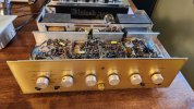
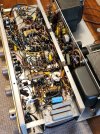
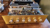
I recently picked up three Altec A7/MR 994A VOTT speakers. My plan was to experiment with the center channel option on my HH Scott 222B. I started looking at some HH Scott mono amp options. A friend mentioned haven a super clean 210D integrated mono amp. He pointed out the name Hermon Hosmer Scott on the faceplate instead of HH. This piece is in stunning condition. A tech owned it prior to my friend. I see some caps were replaced. There doesn't seem to be alot of info on this D version amp. I believe the chassis had a tube layout tag but I only see the glue evidence. I'm cleaning controls and powering it up slowly. Been dormant for 10 years. Does anyone here have experience or info about this 210D amp?
 

Attachments

  • 20260513_185319.jpg
    20260513_185319.jpg
    119.3 KB · Views: 60
  • 20260513_185319.jpg
    20260513_185319.jpg
    119.3 KB · Views: 56
  • 20260513_185343.jpg
    20260513_185343.jpg
    148 KB · Views: 52
  • 762eb772-b703-47e2-86d0-5442ad057ff3.jpg
    762eb772-b703-47e2-86d0-5442ad057ff3.jpg
    209.4 KB · Views: 53
Register to hide this ad
Thanks. I did find a little info. I was still wondering about personnel experience with this unit. I will load tubes in the morning and report back.Thanks again. Rick
 
Last edited:
Will Do. I finished the slow power up last light. Loaded the tubes and was very pleased on how quiet it was on may test speaker. Tomorrow I will hook it up to the A7/MR and give more details on sonics. Thanks. Rick
 
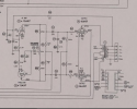
While a copy of the schematic is available on the internet from various host sites, none of those show circuit voltages (as designed). Any help in finding a full manual or more complete version of the Scott diagram would be appreciated, likely by more than just a few participants.

It is possible to measure everything once a unit is up and running with reasonable plate currents and grid voltages, but knowing the original design intent is undoubtedly more valuable.
 
Looking at this schematic, the 6V6's must be tied to a fixed bias source off the schematic. It shows 20 volts on the grids. It must mean -20 VDC? The cathodes show 0 volts but have no ties to ground. Not a dig, just thought I'd point this out.
 
I did try 3 channel. It was awesome until the 210D started distorting (Red Plating) Thats why I didn't report back. It appears the coupling caps were changed at some point,
The amp section design makes testing real hard. You must take multiple layers of plates apart to separate the amp section. Before testing can be safely done.
 

Attachments

  • 1000038959.jpg
    1000038959.jpg
    289.9 KB · Views: 8
  • 1000038958.jpg
    1000038958.jpg
    269.5 KB · Views: 8
Its back bias, yes it should be negative at the grids, and yes the cathodes ought to go to ground. Unfortunately like all schematics they aren't completely reliable so there is an amount of judgement and experience that has to be employed.

Back bias resistor and bypass cap is highlighted since its probably shrunk too far to read here. There are also two 12AX7 heaters in series to ground in parallel with that resistor that are carrying most of the current. Functionally this is little different than cathode bias, except its current draw of every tube in the set vs just the output tubes. It should be more stable from idle to max output since there are extra tubes pulling current on it but it still relies on current flow through the tubes to make it all work.

1790092670705.png


Looking at this schematic, the 6V6's must be tied to a fixed bias source off the schematic. It shows 20 volts on the grids. It must mean -20 VDC? The cathodes show 0 volts but have no ties to ground. Not a dig, just thought I'd point this out.
 
@gadget73 - Thank you for the link to the 210C version. That is closer to what is the reality for the 210D being worked on. It also helps build the archive.

The one item of interest is that the commonly available diagram for the 210D shows three (3) 12AX7 filaments in series as a bias source, comprised of V1, V2, and V6. That would tend to point toward something closer to -36V as a raw value. The resistances downstream of that would likely drop (increase?) that to something closer to the specified bias levels for P-P arrangements of the 6L6G outputs according to GE and Tung Sol data sheets.
 
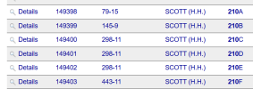
Oddly that folder is what Sams says is for the 210D, honestly I didn't even notice that the schematic itself says 210C.

1790099521052.png

I guess they felt that the C,D, and E were close enough to use a single schematic.

6L6 outputs, ~20v is about right at the plate and screen voltages the schematic calls for but the voltage can be anything really. The total back bias can be whatever, just have to tap somewhere between max negative and 0 to get the right grid voltage. It takes away B+ of course, can't just get "free" voltage but it wouldn't be difficult to run 3 tubes instead of 2 here, just have to accept about 12 volts less on the plate and screen, and add a pair of resistors to set the grid voltage.


unless 6L6 is also a typo, since there is no 6L6GT that I'm aware of.

Sams unfortunately did have some errors. Still better than nothing but you really have to be careful with them sometimes. Mfg schematics are generally more accurate but I've run into mistakes or at least variations on those plenty of times too.
 
I have seen tube designations use "GT" as an indicator of "glass tube" in applications where MIL/industrial tubes would be metal cases.

Coincidentally, the commonly published schematic for the 210D clearly indicates a 1614 output tube in place of the 6L6 or 6L6GC. The 1614 (RCA, GE, Raytheon) is in essence a ruggedized version of the 6L6 for 80MHz operation, is pin compatible with the 6L6, and in some data sheets has slightly higher ratings. It's not that a 6L6 wouldn't plug in and operate, but the bias scheme being fixed for one may not be optimal for its cousin.
 
Last edited:
6L6GT is the original 19w 6L6 in a Glass Tubular bottle. 6L6G should be a coke-bottle tube.
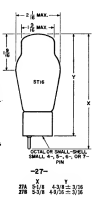
Actually no such thing - GT has a glass tubular T-9 envelope, 1 1/18" diameter. 6L6G is ST-16, GA is ST-14, GB and GC are T-12 - 1 1/2" (number is max diameter in 1/8" increments).
 
^^ this is the 6L6 family I'm aware of as well, have never seen reference to a 6L6GT anywhere. 6V6GT for sure though. Pictures in the Sams folder look like 6L6G tubes. Voltages look very near to 6L6G datasheet values too.

1614 and 6L6 are the same thing, other than some specific transmitter duty ratings. They would bias the same and all that fun stuff. This is also nearly cathode biased, so it won't be as fussy about tube variations as a true fixed bias design. Most of the current flow through the back bias resistor is from the output tubes, the 12A*7 tubes and the 6AL5 don't flow all that much.
 
The self-bias design is a given in the topography of the 201D, the question asked originally for a clean schematic was to verify the values of some of the resistors shown in the cathode/grid connections. One of them is clearly 330K, but the other is so blurred that it is impossible to decipher. Measuring to see how much drift there might be in a 70+ year old unit basically requires knowing what it should be originally, and markings are very difficult to read in the congested chassis.
 
Actually no such thing - GT has a glass tubular T-9 envelope, 1 1/18" diameter. 6L6G is ST-16, GA is ST-14, GB and GC are T-12 - 1 1/2" (number is max diameter in 1/8" increments).
6L6-RCA75.png
^Yup, 6L6GT is a thing. agreed. (all from RCA 1975 manual)

6L6 ST16.png
6L6G, ST16. Coke-Bottle shape. Yup.

6L6 T9.png

Yup. 6L6GT, tubular bottle..
Literally what I said.
Literally what you said.
Separated by a common language. too bad...
 
Back
Top Bottom