• The move to the new server is done. There are some software and database maintenance updates in process. This has us passing the hat around to help out. We appreciate any donations. Seriously, even a dollar helps. The payment page may be found here - https://www.audiokarma.org/support.html

HH Scott 299c

The control grids are close.
What's the current through each power tube looking like?
Can you install a 10. Ohm resistor to measure that.
I seem to remember about 24 or 26 volts on the control grid, but I'm not. Finished with coffee yet for the morning. Suffice to say the control grid voltage is less important than the current it causes through the tube.
You make your adjustment based on that number and the actual control grid voltage lands where it lands.
 
The control grids are close.
What's the current through each power tube looking like?
Can you install a 10. Ohm resistor to measure that.
I seem to remember about 24 or 26 volts on the control grid, but I'm not. Finished with coffee yet for the morning. Suffice to say the control grid voltage is less important than the current it causes through the tube.
You make your adjustment based on that number and the actual control grid voltage lands where it lands.
Train, I put an order in to Mouser for resistors.
Several of these old carbon comps out of spec.
Still need to wire in the Standee 120 ohm where the hazardous one sticks up.
Whoever was in this unit before me did a good job of installing a sand cast resistor in what I now have figured out is most likely the chassis strengthening bracket. I’ve marked it close to 80 ohms.
This evening after work I’m going to see what the current draw is now with a digital bias meter.
The high voltage concerns me. I realize and also suspect these tubes not conducted enough current plays a major role here. One pair test 100 on my Mighty Might 150, two other test lower.
Also the last unit like exactly like this one was discussed in 2017 by @jiml2001 , his voltages weren’t this high IIRC.
I was intimidated by this before I started, with all the excessive voltage and strange heater arrangement.
I’m going to email Jim McShane today and ask for his opinion on a quad 5971.
 
Edit: that would be -29 at all control grids.
The control grid voltage is usually in the range of -20 to -23 volts to get the plate current in the range of 35ma with 450 volts on the 7591 plates for old vintage US made tubes.
I think your assumption that the plate voltage will come down when you get more current to flow is a good one, so I'd say you need to work on lowering the (negative) bias voltage to get your amplifier running properly.
 
The control grid voltage is usually in the range of -20 to -23 volts to get the plate current in the range of 35ma with 450 volts on the 7591 plates for old vintage US made tubes....
That sounds just about correct. I have no experience with any but USA or Japanese manufactured 7591/7591A tubes. Coin base are ugly but are excellent performers.
 
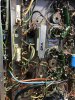
1A2E5F73-5C49-4828-9A1C-D9EF11A1B739.jpeg Here’s where I currently stand. I’ve taken a gamble on a couple singles off that auction site 7591’s.
Should be here in a couple more days.
The better test pair (100) each I’ve moved into one side. The lower pair (98 & 95) puts me at 16.9 16.8 respectively. Should be 0.22 according to what I read for total 70mA draw per pair.
across new installed 3.32 CMF60’s.
This is with pots balanced even out sides.
488 anodes, 460 cathodes 121.8vac line and a pair CL-80 feeding PT primary windings.
I have -41.5 at first 12AX7…-10.5 last.
6.4ac to 6.37 furthest point from PT heaters.
The “death trap” 100ohm originally sticking up above chassis is now gone, replaced with the 120 I had fortunately found digging around in the parts house I frequently visit in H-town. Also got rid of the other 80ohm/25watt that had been so cleverly hidden & secured underneath the chassis strengthening bracket in series.

The Cericaps removed feeding the grids checked fine at full voltage with my IT-28. No leakage
But got K42y-2 for good measure. I’m inclined to leave all others in place.

The 18ohm droppers on the bias supply can had all drifted up 20. I could only find some gold band 5% Allen Bradley laying around while rebuilding that can.
Better at 18.5ohms. Left at that.
Playing around with resistors in the parts bin, and voltages, settled on DON’T LAUGH ——Honda?? 2watt 36 ohm wire wound that fit between pins 2-6 5ar4 socket.

Went ahead and got rid off the unreliable old stock 4uf’s I had first rigged in with “Kwikette’s”.

There’s only one unattended to 30/30 500 can cap.
It’s good for now, and also the easiest one to pull/re-stuff.

So in summary, I am quite amazed at how quite this integrated amp performs. Sounds amazing, even with less than perfect matched output tubes. Putting out less power, then could be achieved. Easily can tell it beats my restored Fisher 400!

Will see if the 7591’s I took a chance on test any better, bias up tighter.

 

Attachments

  • 4FF3AF4E-F7C0-4E92-81FA-B44165BA47D3.jpeg
    4FF3AF4E-F7C0-4E92-81FA-B44165BA47D3.jpeg
    179.3 KB · Views: 31
  • F1EE3186-64D0-4BD6-8D06-F1BE2A14227D.jpeg
    F1EE3186-64D0-4BD6-8D06-F1BE2A14227D.jpeg
    115.3 KB · Views: 30
  • 415CD04C-FDF6-4BD3-8DA0-97F35941EE63.jpeg
    415CD04C-FDF6-4BD3-8DA0-97F35941EE63.jpeg
    126.2 KB · Views: 30
  • 0AFAD7E0-0AAC-4720-9B45-110BBF42E1CA.jpeg
    0AFAD7E0-0AAC-4720-9B45-110BBF42E1CA.jpeg
    128.1 KB · Views: 30
  • 2D1A7D41-95FF-4C4F-8871-3EBEBC5245E6.jpeg
    2D1A7D41-95FF-4C4F-8871-3EBEBC5245E6.jpeg
    91.4 KB · Views: 29
  • 8156EAEE-5B87-451A-8962-5D120FAAE750.jpeg
    8156EAEE-5B87-451A-8962-5D120FAAE750.jpeg
    73.2 KB · Views: 29
View attachment 2450343 Here’s where I currently stand. I’ve taken a gamble on a couple singles off that auction site 7591’s.
Should be here in a couple more days.
The better test pair (100) each I’ve moved into one side. The lower pair (98 & 95) puts me at 16.9 16.8 respectively. Should be 0.22 according to what I read for total 70mA draw per pair.
across new installed 3.32 CMF60’s.
This is with pots balanced even out sides.
488 anodes, 460 cathodes 121.8vac line and a pair CL-80 feeding PT primary windings.
I have -41.5 at first 12AX7…-10.5 last.
6.4ac to 6.37 furthest point from PT heaters.
The “death trap” 100ohm originally sticking up above chassis is now gone, replaced with the 120 I had fortunately found digging around in the parts house I frequently visit in H-town. Also got rid of the other 80ohm/25watt that had been so cleverly hidden & secured underneath the chassis strengthening bracket in series.

The Cericaps removed feeding the grids checked fine at full voltage with my IT-28. No leakage
But got K42y-2 for good measure. I’m inclined to leave all others in place.

The 18ohm droppers on the bias supply can had all drifted up 20. I could only find some gold band 5% Allen Bradley laying around while rebuilding that can.
Better at 18.5ohms. Left at that.
Playing around with resistors in the parts bin, and voltages, settled on DON’T LAUGH ——Honda?? 2watt 36 ohm wire wound that fit between pins 2-6 5ar4 socket.

Went ahead and got rid off the unreliable old stock 4uf’s I had first rigged in with “Kwikette’s”.

There’s only one unattended to 30/30 500 can cap.
It’s good for now, and also the easiest one to pull/re-stuff.

So in summary, I am quite amazed at how quite this integrated amp performs. Sounds amazing, even with less than perfect matched output tubes. Putting out less power, then could be achieved. Easily can tell it beats my restored Fisher 400!

Will see if the 7591’s I took a chance on test any better, bias up tighter.

I have a few observations that might be helpful to you:

You show 460 for Cathode voltage.
That doesn't sound right.
Is that the voltage on the Screens (pin 8) ?

From you underside pic this looks like the version of the 299c that had current sensing resistors in series with power supply line to the Anode plates.
Later versions had them in series with the Cathode ground line but the resistor size and current measurement are the same.
The usual caution about working with high voltages apply.
A practical way to measure the DC Balance is to get the anode plate voltage equal between output tube pairs in each channel using the balance pots.

I'd recommend getting the bias voltage correct before you risk subjecting your pricey 7591's to overmax plate current.

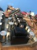
It looks like someone installed a shield along the back end of your chassis near the input jacks.
I haven't seen that before and I don't thing it hurts anything.
It's possible a previous owner was chasing a hum and used the shield to try eliminate it.
I've got a few Scott amps of this vintage and all are very quiet with regard to background noise without the need for additional shielding.

It looks like you're making good progress and you'll have a nice sounding amp when you're done !
 
@Pablodeux, correct..460 at pin 8.

Looks like that shield is factory with the same type rivets as used elsewhere?

I’ve reservations about adding separate 10ohm current sense resistors.
I have done them in the past, the Sansui 500a & Fisher 400. But is a bit confusing on this amplifier, for me. For the “ground” which is actually floated a few volts above ground? Believe I’ve read that somewhere.

With the black wires supplying negative voltage from the bias pots combined with not only one, but two “cathode”?? resistors. A 470k and 270k.
I’ve tried to find clear pictures of where this has been done, but haven’t found.
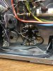
I know I could use the socket’s empty ground lugs. Still unclear, even after reading “how” it’s done.39E63AA6-F847-40B5-A4AC-788662665924.jpeg
 

Attachments

  • 17C22E98-6D30-49AA-A530-BD3FD8F9B961.jpeg
    17C22E98-6D30-49AA-A530-BD3FD8F9B961.jpeg
    115.3 KB · Views: 8
@Pablodeux, correct..460 at pin 8.

Looks like that shield is factory with the same type rivets as used elsewhere?

I’ve reservations about adding separate 10ohm current sense resistors.
I have done them in the past, the Sansui 500a & Fisher 400. But is a bit confusing on this amplifier, for me. For the “ground” which is actually floated a few volts above ground? Believe I’ve read that somewhere.

With the black wires supplying negative voltage from the bias pots combined with not only one, but two “cathode”?? resistors. A 470k and 270k.
I’ve tried to find clear pictures of where this has been done, but haven’t found.
I know I could use the socket’s empty ground lugs. Still unclear, even after reading “how” it’s done.View attachment 2450477

I can see your dilemma with the way the socket is wired on your 299C with the 270K and 470K resistors attached to the socket lugs.
I have an early model LK 72 without balance pots or bias adjust pots and the resistors are mounted on tab strips with wires running to socket lugs.
The values of the resistors are different since there is no provision for controlling tube current.
They must have really been cutting cost corners when they went this way on the 299C, and later versions of the amp such as the LK72B, and early and late versions of the 299D went back to using tab strips, so it's much easier to see what's going on.

You can peruse all the similar schematics on AK database, but at this point it might get more confusing for you.
I think you will have good results if you go to the schematic for the 299D (s/n 249780 and up) and use tab strips with resistance values used there. However, they pull the voltage going into the bias adjust pots from the 1st cap on the bias can cap, and its -58V.
If yours is in the -43V range you could use the LK72B schematic as a model instead.

I have added 10ohm sensing resistors to an LK 72B and a late 299d and all that was necessary was to first remove the wires from pin 5 of the power tube sockets and the 3.3 ohm 1 watt resistor for both channels.
Then I added one tab strip located between the power tube sockets for each channel, so was located equidistant between the pin 5 lug for each socket.
A 10ohm resistor will reach the tab strip from each #5 socket lug this way.
A single ground wire for each pair of resistors was run to a common circuit ground terminal for each channel.
Four test point jacks can be added to the top of the chassis with a wire running to socket lug 5 from each one.
This would enable you to check and adjust bias and DC balance from low voltage points without going under the chassis.

My amps had the 3.3 ohm resistors on the cathode end of the circuit so it was necessary to remove them.
Since yours are in the power supply line to the plates you could probably leave them, but I'd remove them since they will no longer serve a purpose.

I hope I didn't make this too confusing !
 
That shield is standard for HH Scott amps, likely meant to improve the S/N ratio of the low level inputs.
 
That shield is standard for HH Scott amps, likely meant to improve the S/N ratio of the low level inputs.
I looked at my amps and I see they have it too.
I was fooled by the way the light flashed off of it made me notice it, where I didn't before.
 
I looked at my amps and I see they have it too.
I was fooled by the way the light flashed off of it made me notice it, where I didn't before.
Exactly. Note that the inputs are physically very near the output transformer leads. The engineers at Scott knew what they were doing.

I have had several amplifiers that the previous owner(s) had made what they must have though were "improvements" to the design. For whatever reason, I had two amplifiers that had the balance control either removed or replaced with some two-pot contraption. Lucky for me, I had a few of the exact controls that were in the original design and was able to rewire the amp back to the design configuration. Guess what? It worked perfectly after that rubbish was removed and sounded as it should.

For what it's worth, the only "modifications" that I do are to replace aged and/or defective (read worn out) parts and put it back to stock. It just worked; it just works like original.

Again, YMMV...
(OK, OK, down off of the soap box!)
 
Looking at that photo again, I realized there is also the small shielding plate screwed to the chassis between the output tubes and the output transformer wiring. That’s another standard practice for Scott amps.
 
Looking at that photo again, I realized there is also the small shielding plate screwed to the chassis between the output tubes and the output transformer wiring. That’s another standard practice for Scott amps.

Yes. It is difficult with the lack of real estate on the rear of that slim chassis to keep AC input, signal input and signal output separated. You don't want the input, especially magnetic phono and tape head near the output. And you especially don't want it near the AC power wiring. Some Scott amplifiers have the Power switch leads inside of a shield which is grounded; others have the switch wiring twisted tightly and along the side rail of the chassis. That is done on purpose and to help reduce as much induced hum as possible.

You may have also noticed that the AC filament voltage to the output tubes as well as the phase inverter/AF amp tubes (7199,6U8/6BL8,6GH8) is tightly twisted to reduce the AC field. Notice that the preamplifier tubes, 12AX7, are supplied with a DC voltage. Scott had a plan and it just worked. Flying leads, high up in the air can cause issues. Wires are better tucked down and next to the chassis, as much as possible.
 
Thanks for the suggestions and information @Pablodeux and @kvflyer. AK is a treasure trove with wealth of information. I’m always more research , reading time invested. More so doing this, than hands on.

From the moment I removed the bottom I had the impression that the “other” bracket that was holding the 70ohm 25watt was intended for this purpose.
However following enough threads I finally realize it’s used for chassis strengthening and/or now shielding.
Knowing that resistor was added by someone only after seeing a few units containing nothing there.
I thought maybe some value resistor might had originally used the spot. But all along, the extra wiring just didn’t add up. (Some other Scott units do have cement dropping resistors under chassis) what did I know..
Just luck that I tend to pick up vintage hard to find parts when I see them. The Standee 120ohm wasn’t for any particular project. I had it before I acquired this 299c. @kvflyer suggestion , seems to have come in handy. It’s 10vdc and few ac voltage drop needed. To rid the “death trap” rigged before. Not by me!

One NOS GE arrived yesterday, tests right at 100 on my MU150. Waiting on two more singles supposed to be NOS as well. Will wait until I get at least another, tests this high. Will see how they balance out and bias across the 3.3 ohm resistors.

Took a chance on a small lot 6BL8. Tested and paired. Now have a nice pair BVA Mullard, pair of Amperex Germany that flash, Amperex Holland make up the rest. Needed as one original Tele lit the short light barely enough to see. Then gave up right channel after a little listening.
The NOS green label Sylvania 6U8A don’t sound bad though.
It’s funny how many of those 6U8 sleeves one can accumulate just from old tv tube caddies.

Will keep updates as my better 5791’s arrive.
 
Now, thanks to @GD70 10ohm current sense resistors inquiries. Maybe I can figure out mine. Circuit wise a little different, but see clearly how to go about it.

Now, about my 495 plate voltage 470 screens. I’m concerned even with more negative bias voltage (need to try a higher value than the 2 watt 36ohm) .
Minimum range on my pots dialed down all the way is -23ish. I think I should be around -18 ?
Don’t think chasing NOS or ANOS is beneficial.
I did this with the Fisher 400 until I finally ended up with a quad 7868’s from 30mA - 36mA. Good enough it sounds wonderful.

Any thoughts on which brand current production 7591 to purchase if it comes down to it?
Have the metal case, so height has to be considered. Also smaller bottles if possible? Heat transfer next to OP transformers.

Last thought, could a zener be added to drop overall B+ ?
 
The current production tubes which work the best are 7591 "Tung Sol" reissues
Get them from Jim Mcshane when he has stock. He does the matching "in house" and can walk you through anything else that needs done. He's an incredibly knowledgeable resource.
I can't honestly remember what the exact grid voltage is for each individual power tube, and it's the less relevant of the 2 numbers.
You need to know the current at the cathode, which requires a simple modification.
10 ohm resistor on the cathode.
 
Look at the schematic for the 299C and the 299D for a better idea of what voltages should be where, since those models are similar to the LK72 but were factory-built as opposed to the LK series as kits. Both are based on 7591 output tubes.

The LK72A schematic on the HHScott.com site doesn’t provide as much information as the 299C schematic. There’s also an error on that LK72A schematic. At R206 it shows a voltage of 425 but the other end of that circuit at the output transformer that’s shown as 475. The bias voltage on the 299C on the 7591 pin 6 is shown as being -18.5V, so that’s where yours should approximate. Of course, that’s based on a plate voltage of 420V.

The 299B shows a simpler bias test circuit, albeit using 18 Ohm resistors where 10 Ohm would be mathematically easier to calculate the bias current.

Keep in mind that Scott states on the schematic that voltages can be +/- 15% with a wall outlet voltage of 117VAC.
 
My attempt to achieve less negative bias is getting me nowhere fast. I had removed the original 18ohm (drifted up to 20) CC from between pins 3 & 7 5AR4 and soldered in a small 2watt 36ohm wire wound. My range is -24.4 ~ -27.5. Down from -25.85 ~ -29.31. Bias voltage now being taken with the 5Ar4 out, at 117vac. Am I causing damage to the other tubes, heaters lit, when changing resistor values?
I am shooting for a goal of 19-22
 
Back
Top Bottom