• The move to the new server is done. There are some software and database maintenance updates in process. This has us passing the hat around to help out. We appreciate any donations. Seriously, even a dollar helps. The payment page may be found here - https://www.audiokarma.org/support.html

HH Scott 299c

Hi, @Pablodeux, @Dave451 helped in a 2017 thread. Scott 299c bias adjustment ?. Exact problems, same strange 299c version amplifier.
To revisit that old thread, I have a few general questions. Hoping to get some answers. I really need to wrap this one up.
I don't mid going through all the trouble of adding sampling resistors. But I need to get the overall - voltage down first.
It's easy enough to see current drawn across the 3.3ohm resistors for now.
 
Hi, @Pablodeux, @Dave451 helped in a 2017 thread. Scott 299c bias adjustment ?. Exact problems, same strange 299c version amplifier.
To revisit that old thread, I have a few general questions. Hoping to get some answers. I really need to wrap this one up.
I don't mid going through all the trouble of adding sampling resistors. But I need to get the overall - voltage down first.
It's easy enough to see current drawn across the 3.3ohm resistors for now.

Increasing the resistance of the first dropping resistor after the rectifier (I think you have a 120 ohm resistor there now) would be the shortest path to lowering that plate voltage.
Lowering the voltage there should not effect bias supply voltage, since it's derived from a separate transformer winding.
You can calculate the current by measuring the voltage drop across the resistor currently in place, calculate how much more resistance you need to get the voltage drop you want, and add an additional resistor in series to drop the voltage.
Knowing the current and resistance you can calculate the wattage of the additional resistor, and I'd double the calculation to decide what wattage resistor to use.
You can use a chassis mount resistor, the type with an aluminum heat sink, to keep the resistor under the chassis.

I know I have seen some comments on high voltage in Scott amps from Dave Gillespie, so you can do some searching for threads he has contributed to, for some first hand knowledge on the topic.
I think some mention can be found in the Scott 208 amplifier threads.

One more comment:
Did you adjust your DC balance pots by getting the plate voltages equal for each pair of output tubes ?
Just adjusting the pot to its midpoint won't ensure the current across the 3.3 ohm resistor is getting equally distributed to both tubes.

I hope this helps !
 
Thanks @Pablodeux, it’s the negative bias that I am concerned with. Seems I can’t keep using more resistance on the first bias dropper. I’m at max because it also starts lowering the heater feed. I was just clipping in larger values to watch bias pot range.
The 2 watt 36 now reads 38ohm. Maybe from heat?
I’m starting to think alternative measures. Change pot values for more swing? I have one more 7591 (nos) should be here today or tomorrow.
Yes, I have been trying to get as close to 0 volts between the plates with balance.
I don’t don’t quite understand the figures Dave came up with in measuring across the 3.3 resistors.
Say I have .180 X 3.3 .594 *2 = 0.297. That’s almost 30mA pair. See where this is headed? Way too low.
Even if adding.3mA per tube for cathode current.
Please have a look at the 2017 thread Dave’s math.
Seems different.
I might also put back in one of those extra wire wound I had removed from under the bracket. Although I don’t recall it doing much for the high B+, still something to think about.
I’m almost at the point putting an ad on BT for a power transformer.
Thanks again Pablo!
 
Last edited:
5Y3 vs 5AR4 overall B+ drop? Don't know if the first 30 + 30 / 60uf filter is too much?

It looks like you got the math from Dave's thread correct, and that you should be getting ,23/.24 volts across the 3.3 ohm resistor.
There is a thread from 2015 that Dave helped out with, that is specific to the 299C and I think it's worth your time to read it over carefully:
https://audiokarma.org/forums/index...my-scott-299c-bias-and-dc-balance-pots.677637
Reply 16 is where it really starts getting relevant to you issue.

I think I now see the problem you are describing and it's not what I thought you were asking about before.

The 1st thing I think we need to pay attention to is the 36 Ohm resistor you said you installed between pins 2 and 6 of the 5ar4.
I don't think that belongs there and recommend that you remove it.

Looking back thru this thread, it looks like you were searching for a 33 ohm resistor early on, but I'm not sure what started that search.
The model LK72 and LK72B which were the kit versions of the 299 amps used a 33 Ohm resistor between the output of the bias rectifier and the 1st section of the bias supply cap.
Your 299C was produced between these models and judging by your your problem with too much negative bias voltage, adding resistance at that location will result in less negative bias voltage.

As your amp sits now, what is the bias voltage at the output end of the 18 ohm resistors on your bias can cap?
Is this the same location where the voltage is sent to your bias pots from ?
The DC voltage for the preamp tubes at the output should be -44V/-45V and if it's running high along with the bias output, your 36 Ohm resistor might come in handy.

Lets go one step at a time, and look at where you are after you measure the bias output voltage.
 
It looks like you got the math from Dave's thread correct, and that you should be getting ,23/.24 volts across the 3.3 ohm resistor.
There is a thread from 2015 that Dave helped out with, that is specific to the 299C and I think it's worth your time to read it over carefully:
https://audiokarma.org/forums/index...my-scott-299c-bias-and-dc-balance-pots.677637
Reply 16 is where it really starts getting relevant to you issue.

I think I now see the problem you are describing and it's not what I thought you were asking about before.

The 1st thing I think we need to pay attention to is the 36 Ohm resistor you said you installed between pins 2 and 6 of the 5ar4.
I don't think that belongs there and recommend that you remove it.

Looking back thru this thread, it looks like you were searching for a 33 ohm resistor early on, but I'm not sure what started that search.
The model LK72 and LK72B which were the kit versions of the 299 amps used a 33 Ohm resistor between the output of the bias rectifier and the 1st section of the bias supply cap.
Your 299C was produced between these models and judging by your your problem with too much negative bias voltage, adding resistance at that location will result in less negative bias voltage.

As your amp sits now, what is the bias voltage at the output end of the 18 ohm resistors on your bias can cap?
Is this the same location where the voltage is sent to your bias pots from ?
The DC voltage for the preamp tubes at the output should be -44V/-45V and if it's running high along with the bias output, your 36 Ohm resistor might come in handy.

Lets go one step at a time, and look at where you are after you measure the bias output voltage.

On the variac at 116vac -47.5 on the can cap.
Yes, I nulled both pair outputs to 0 volts or very close.
On wall voltage, 122vac it’s -50.4.
Heaters on full voltage -41.7 ~ -10.65
This is with the 36ohm resistor pins 1 & 7.
 
On the variac at 116vac -47.5 on the can cap.
Yes, I nulled both pair outputs to 0 volts or very close.
On wall voltage, 122vac it’s -50.4.
Heaters on full voltage -41.7 ~ -10.65
This is with the 36ohm resistor pins 1 & 7.

I expected for the bias voltage tap coming from the can cap to be at the same potential as the source for the heater filaments (-47v for both).
There must be some resistance between the two points where you took the measurements, since you said the filaments are at 41.7V.
Can you take a picture of the bias can cap showing where the source wires for the Bias pot and heater filament supply are attached ?

I'm not sure where the 36 ohm resistor is attached.
Earlier post said between pins 2 and 6 of the rectifier tube, so what does pins 2 and 7 refer to ?

If we keep plugging away we'll get to the bottom of the problem.
 
Pablo, my thinking, correct me if I’m wrong. But less negative voltage from the bias pots lets more current flow the power tubes. Why I increased the 18 up to 36ohm.
 

Attachments

  • image.jpg
    image.jpg
    148.4 KB · Views: 13
  • image.jpg
    image.jpg
    151.5 KB · Views: 12
Pablo, my thinking, correct me if I’m wrong. But less negative voltage from the bias pots lets more current flow the power tubes. Why I increased the 18 up to 36ohm.

So the socket in the 2nd picture is for the 5AR4 rectifier, and the bias voltage is coming off of it ?
If that is the case, is the 5AR4 suppling both the filaments and bias pots ?
All of the Scott tube amps I've seen have a separate solid state rectifier, either selenium or later a silicon rectifier.
There is a separate winding for the bias supply that comes off the power transformer that supplies the voltage for the solid state rectifier.
The selenium rectifiers have been known to have reliability issues, and can be toxic when they fail, so most have been replaced with silicon bridge rectifiers.

Verify that the bias supply is coming off the 5ar4 before I get too far down this path, and we'll try to figure out where to go from there.
 
Ok. Not to confuse you. I have the 18 ohm back as found. Voltages taken at 117. There is -28 feeding the bridge 2 legs. -56 leaves the other leg. Feeds the 18ohm, then back to the reservoir. Actually splits on pin 3 5AR4 via the junction 47k and now 18ohm.
There is 56 to 53 volt drop across the 18ohm and -46 feeds the bias pots via pin 5 5AR4 tie point
 
Here is the diode bridge.
I found another AK thread that involves a version similar to yours:

https://audiokarma.org/forums/index.php?threads/scott-299-c-information-needed.674995/

It appears Scott cut some costs on that version by utilizing unused terminals on the 5AR4 socket to anchor some of the bias supply connections, but it's not borrowing any power from the 5AR4, just utilizing unused real estate for the parts of the bias supply.
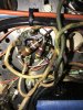
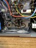
Where does the purple wire attached to terminal 5 of the socket go ?
I'm assuming the red wire attached to terminal 1 comes from the power transformer, and that the white and red striped wire is the one that leads to the bias supply cap.
Am I correct ?

We may be making progress.
 
All correct sir. The purple wire feeds the bias pots.
All boils down to trying to use these NOS purchase tubes, singles at that is not cutting it. I’ll have to order Tung-Sol reissue. Jim McShane is out of stock.
Or I would have long ago had a quad.
Don’t know the best trusted seller.
 
All correct sir. The purple wire feeds the bias pots.
All boils down to trying to use these NOS purchase tubes, singles at that is not cutting it. I’ll have to order Tung-Sol reissue. Jim McShane is out of stock.
Or I would have long ago had a quad.
Don’t know the best trusted seller.

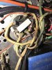
I don't think the Old Stock tubes are the problem, and they can be expected to be more durable than the new Tung-Sols.
It looks to me like you need a larger dropping resistor in place of 4.7k Ohm resistor that goes from the red wire (bias rectifier output) to the purple wire ( bias pot supply) at terminal 5 of the 5AR4 socket.
This will lower the bias pot input independent of the filament voltage.

I see two ways to go here but there is 3rd option which would correct the original problem at it's root cause.

1) If you replace the 36 ohm resistor with the 18 ohm one that was there before, I think it will raise the filament voltage some where near where it belongs, and we can then measure the current across the existing 4.7K resistor to determine what size is needed there.

2) Leave the 36 ohm resistor in place, live with the lower filament voltage, which will probably work if you still have the Telefunken 12Ax7's the amp came with when new.
I don't think new production 12AX7's will behave well with reduced filament voltage.
Then measure the current drop across the 4.7K resistor to determine what size resistor will be needed to lower the bias pot input.

3) The likely cause of your problem is that the new silicon bridge rectifier puts out higher voltage than the original selenium rectifier, and an additional voltage dropping resistor is needed in series with the red wire that goes to terminal one of the 5AR4 socket.
You might find that the 36 ohm resistor is a better fit as the dropping resistor.
You then might find that the 18 ohm resistor can be put back between terminals 1 and 7 of the 5AR4 socket and get the full filament voltage as well as reduced bias supply voltage.
If you start by using the 36 ohm resistor this way, we can see if any further resistance changes need to be made to get the Bias and filament voltages where they belong.
 
Thank you @Pablodeux. I like the heater voltage better with the 18 (closer to 19) raises the filament voltage to the Telefunkens a full volt. End of string it’s 11.4. Was 10.4 with the 36ohm.
When I get more time I will see what increasing resistance of the 47k does for the bias pot voltage.
 
Awesome @Pablodeux ! It took a 12k dropping resistor to the bias pots. My 7591’s balanced to 0.
.22mA across the 3.3 resistors.
Plates 465 screens 439. Heaters -45 ~ 11.5 Teles.
6.28vac to 6U8a.
This is at wall voltage 121 this morning.
I do believe all is well, and going to call it a done deal.
Thank you for getting me going in the right direction man, you’re the best!
 
Beautiful. Tubes show way more color in the dark with the cell phone. Naked eyes, they look much less orange. Sounds fantastic.
 

Attachments

  • image.jpg
    image.jpg
    91.6 KB · Views: 19
Back
Top Bottom