• The move to the new server is done. There are some software and database maintenance updates in process. This has us passing the hat around to help out. We appreciate any donations. Seriously, even a dollar helps. The payment page may be found here - https://www.audiokarma.org/support.html

HH Scott LK-72b burning power filter cap resistor

salperta

Member
Hello to all.
I'm working on restoring a Scott LK-72b. I am fairly new to this, so please know that I will probably make mistakes, but I am very glad to learn.

First thing I did before firing it up was to replace all of the capacitors including the can caps. I also replaced the selenium rectifier.

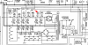
At first, after finishing the capacitor replacement, I was getting music. The right channel sounded excellent, but the left channel sounded muddy and slightly quieter than the right. So I started looking around, but while I was doing so, the 270ohm 5w resistor (R205 on the schematic) that goes between the positive posts on the power filter capacitor (c204) started burning. .

I first tried replacing the resistor with the same value resistor. When I turned on the amp, right after the light went on, the new resistor began to smoke and glowed red! So it wasn't simply due to a bad resistor.

I then tested the 20ohm 10w standup resister (RWS1) that is before the filter cap. It measured right on 20ohms.

I also checked the output voltages from the power transformer. I am getting 57 volts from the orange wires that go to the solid state rectifier. The green wires, which go to pins 5 and 7 on the 5ar4, read 6.5volts. The yellow wires, which go to pins 2 and 8 on the 5ar4 (and then to RWS1 and on to the filter cap), are reading 5volts. The red wires, which go to pins 4 and 6 on the 5ar4, overload my DMM, but each red wire to the center tap reads 408volts. These readings seemed to correct to me. I pulled the filter capacitor (which I had restuffed with two 33mf 500v capacitors), and tested each on my DMM. After discharging them, they both started low and went up steadily.

I made sure that the 4 x 100/75 cap had the positives wired together and then to ground.

I also tried pulling all the tubes except the 5ar4, and the problem still persists.

I'm a little at a loss as to what to try next. I've read through all the LK-72b threads I could find here on audiokarma, but was unable to troubleshoot this problem, so I thought I'd reach out to the masters.

Many thanks in advance, I greatly appreciate everyone's advice!
 
Register to hide this ad
Can you post a schematic of the power supply? Shouldn't be too hard to figure out once we can eyeball it.
 
Oh yes, of course. I forgot not everybody has it permanently open on their computers.:rolleyes: Thanks in advance for any insight!
LK72B.JPG
 
I tried uploading the entire schematic but I must have found a high-res PDF because it was too large to attach.

partial_schem_LK72B.PNG

**oops, I see I'm late to the party ;) Did you ever get your tubes tested? I'm wondering about the condition of your 5AR4.
 
I tried uploading the entire schematic but I must have found a high-res PDF because it was too large to attach.

View attachment 1763249

**oops, I see I'm late to the party ;) Did you ever get your tubes tested? I'm wondering about the condition of your 5AR4.
We double-posted, I'm thinking his rectifier may have a cathode to filament short. His voltages are all ok as far as I can tell.
 
Yes, I was worried about the 5ar4 too. I don't have another. I tested for continuity with my DMM and am getting continuity only between pins 2 and 8 (filament, with 0.3ohms resistance) and no other continuity, which I think means there are no shorts? But I have a friend with a tube tester who has offered to test it for me, which I will do as soon as I get the chance.

And catmanboo, I'm pretty sure c204 polarity is right--negatives to ground, positives connected with the resister.
 
Last edited:
Either you made a mistake installing the new caps, or something is drawing way too much current from the 415v supply. Measure the resistance to ground of the 415v supply. It should be very high since the only thing it powers are the screens of the 7591s. There's not much that could go wrong in that part of the circuit. My bet would be a wiring mistake, or a defective C204. A heavy load on the 415v supply would also make RWS3 to get hot. If it's not getting hot, then it has to be related to C204.
 
Pics?

Be sure to make sure the capacitors you replaced are not part of the bias and the cans are positive ground. Something is drawing too much current like a short somewhere.

What is your level of expertise? These Scott amps are not for amateurs.

In my experience, it sure looks like you have a shorted capacitor.

C204 could have a shorted section.

EDIT: A resistor that smokes or glows is not the resistor itself but rather something downstream drawing too much current (short).
 
Last edited:
Thank you Andy. I wouldn't be surprised if I made a mistake, but I did my best to double check polarity and good solder joints. Resistance to ground from the two red wires connected to pins 4 and 6 of the 5ar4 is about 30ohms. Not sure if that qualifies as being very high?

EDIT: removed mistaken schematic reading. My bad!
 
Last edited:
The resistor does not power the rectifier... It's the other way around.

That section of the schematic has to be read right to left -- starting with the incomming AC.

Downstream of the resistor is another resistor, but with a much higher wattage rating. It may be taking the same stress without showing it so obviously.

If one of the 7591's has a screen - to - something short, it would have these symptoms. 1st step would be to test all of the 7591's -- especially the weak channed.

Also just double check any work around C204.

Does it smoke the resistor if you run it without the 7591's?

If the filter caps are OK, and the 7591's check out (no shorts), then I would have to turn my attention to an OPT, which is bad news, but less likely.

It's also a possibility that that resistor is miss-rated on the schematic. I don't get having one 3W resistor with 10W resistors on either side of it.
 
Cademan - the only can that I have put positive to ground is the 4 x 100/75. The rest I put negative to ground.

Yes, I was suspecting a shorted capacitor too. I tested the c204 capacitors, and they start at zero and move toward infinity on my DMM. Perhaps I should order a new set for the cans, even though I just put these ones in.

This is not the first tube amp I have rehabbed, but I am certainly not an expert, and am grateful to be learning.

scbrockett - I do have before pics that I am checking my work against. However, I did not test the amp before I started rehab. Perhaps this was a mistake, but I've read on these forums that people suggest not plugging the amps in until at least the caps/rectifier are replaced.

linuxslate - I will get the 7591s tested. However, the resistor still smokes even without the 7591s in place, so I suspect that those aren't the problem. I replaced the resistor with a 5 watt resistor, but I encounter the same problem.

Ugh, I hope it's not the OPT!
 
I know what is connected downstream from that resistor but what do you see connected downstream from it? Something right after that resistor is shorted whether it is that section of the capacitor or something right next down the line.

It wouldn't be the rectifier tube because if it were bad or shorted it would either arc or blow the fuse or both.

Are you going to show us your work. We might be able to see or point out the problem for you to check.

If one of the outputs were shorted, it would be easy to tell either by metering it out or simply disconnecting the center tap and see if it still causes problems.
 
You said: "I pulled the filter capacitor (which I had restuffed with two 33mf 500v capacitors"

I would start there and triple check your work.
 
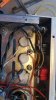
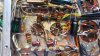
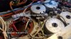
Hello to all. Thank you already for the great advice. Attached are some pictures of my work, thank you so much for offering to take a look at it. Like I said, still learning, thank you. :)

Cademan: What I see downstream of the resistor in question: RWS3, which then connects via a wire to a post on RWS2. An orange wire connects from there to pin 8 on V105. This is bridged to pin 4 on V105, which then connects to pin 8 on V104, etc through the 7591s.

Going back to RWS2, the other post connects to one of the positive posts on C202. Connected to this post is also a wire which connects with pin 5 on V3 via a 15k resistor. Let me know if you'd like me to continue with this description, if it is helpful at all.

jkaley - yes, I suspected the problem was probably right there, but unfortunately I triple checked there and haven't made any progress!

Let me know if any other pictures would be helpful, and thank you again.

20200215_103247.jpg 20200215_103440.jpg 20200215_103448.jpg 20200215_103357.jpg 20200215_103420.jpg
 
I still think section C204 is shorted. Have you checked this with your meter? If shorted, it will show a steady reading that won't move. Something like 1-0 ohms.
 
I have to say, your method of using other components to support each other is not exactly "best practice." With things "floating" like that, cold solder joints become an issue. Installing terminal strips would be best. I'm not slamming you; just pointing that out if you want better results overall.
 
cademan - after discharging, I tested each positive lead on c204 to the negative lead with my DMM. Each starts at zero and moves up continuously.

jkaley - thanks for the tip, and yes, I definitely agree. Originally I left the posts on the bottom of the original cans and connected the cap leads to those, but after finding there were troubles, I got worried that there might be shorting going on inside the wafers (like one lead touching the internal part of a different post or something) so I took them out and hooked it up this way. Maybe this was unnecessary, but I wanted to cover my bases. Terminal strips is a good idea, I'll look into that.

It sounds like the 5ar4 is not the problem, but I've given it to a friend to test with his tube tester anyhow since he offered, so I wont be able to do any more testing til I get it back. Once I do, I'm thinking I'll disconnect the center tap of each OPT and see if the problem still occurs. Hopefully it's not the OPT, but we will see!

Thanks again, I will update when I have the tube back and can perform the tests.
 
Make sure the caps are discharged, then put your multimeter on the ohms setting and measure the points in this picture. As others have said, if you get 0 ohms, you've found your short.

I would think that if there was a short here, the fuse would blow. You did check to make sure it has the correct fuse, right?
testpoints.jpg
 
Last edited:
Back
Top Bottom