To me, it seems there quite a few potential trouble spots here and there. Lots of nicked wire and cold solder joints, bare wire close to the chassis. Do you have a magnifying glass or a pair of reading glasses to get a closer view of the area, they might help with inspection.


You are using an out of date browser. It may not display this or other websites correctly.
You should upgrade or use an alternative browser.
You should upgrade or use an alternative browser.
HH Scott LK-72b burning power filter cap resistor
- Thread starter salperta
- Start date
Hello to all.
Well, thanks to quarantine, I've finally had some time to do work on the amp. I've solved some problems, but one still remains.
1) The burning filter cap resistor was in fact caused by a shorting 5ar4. Replacing it with a new sovtek solved that problem.
2) I also replaced the two 6u8s with NOS RCAs. One was flickering and causing noise. I hoped this would fix the channel imbalance, but it did not.
3) following useful advice given here, I'm using terminal strips to attach leads to the can caps that I restuffed. Hoping this will provide a safer and more permanent solution. The two two-cap cans were easy to manage, but I can't seem to find a good spot to mount a 5-pin terminal strip for the four-cap can. Space is tight down there!
4) I acquired an oscilloscope. (Yay). This allowed me to trace the channel imbalance to the right channel scratch filter. When playing a 1000hz signal thorough the extra input, both right and left wave signals remain equivalent on the scope up until the scratch filter, a "pec-299". The output from pin 6 on the two PECs is drastically different, the right channel significantly reduced in voltage. So I'm thinking the right channel pec is faulty. But, I'm not finding anything in terms of replacements for these things. I wonder if someone might give me some advice on either where to find an equivalent part, or how to replicate the PEC using parts I can find (if that's a thing).
Many thanks as always. I hope everyone is staying healthy and safe during this time.
Saul
Well, thanks to quarantine, I've finally had some time to do work on the amp. I've solved some problems, but one still remains.
1) The burning filter cap resistor was in fact caused by a shorting 5ar4. Replacing it with a new sovtek solved that problem.
2) I also replaced the two 6u8s with NOS RCAs. One was flickering and causing noise. I hoped this would fix the channel imbalance, but it did not.
3) following useful advice given here, I'm using terminal strips to attach leads to the can caps that I restuffed. Hoping this will provide a safer and more permanent solution. The two two-cap cans were easy to manage, but I can't seem to find a good spot to mount a 5-pin terminal strip for the four-cap can. Space is tight down there!
4) I acquired an oscilloscope. (Yay). This allowed me to trace the channel imbalance to the right channel scratch filter. When playing a 1000hz signal thorough the extra input, both right and left wave signals remain equivalent on the scope up until the scratch filter, a "pec-299". The output from pin 6 on the two PECs is drastically different, the right channel significantly reduced in voltage. So I'm thinking the right channel pec is faulty. But, I'm not finding anything in terms of replacements for these things. I wonder if someone might give me some advice on either where to find an equivalent part, or how to replicate the PEC using parts I can find (if that's a thing).
Many thanks as always. I hope everyone is staying healthy and safe during this time.
Saul

andy
Super Member
...
4) I acquired an oscilloscope. (Yay). This allowed me to trace the channel imbalance to the right channel scratch filter. When playing a 1000hz signal thorough the extra input, both right and left wave signals remain equivalent on the scope up until the scratch filter, a "pec-299". The output from pin 6 on the two PECs is drastically different, the right channel significantly reduced in voltage. So I'm thinking the right channel pec is faulty. But, I'm not finding anything in terms of replacements for these things. I wonder if someone might give me some advice on either where to find an equivalent part, or how to replicate the PEC using parts I can find (if that's a thing).
Many thanks as always. I hope everyone is staying healthy and safe during this time.
Saul
The carbon resistors in all of the PECs are probably off value. I had the same problem with my LK-72b. They aren't hard to replicate with a small piece of perf board.

Retrovert
Addicted Member
Excerpt of PEC information I've previously posted.
The PEC's phenolic coating, never a perfect seal even when new, degrades over the years and the PEC absorbs moisture, exactly like the hygroscopic carbon composite resistors and hygroscopic barium titanate capacitors comprising it. (Both carbon-composite resistors and ceramic capacitors components were coated with a phenolic sealant which degrades over time.)
So as far as how one tests a PEC, use the procedure developed by the late Alan Douglas: drop the PEC in the trash can. If it mades a thunk or thud, it's definitely bad and should be replaced. If it makes a tink it's going bad and should be replaced, if it makes no sound it wasn't dropped it into the can hard enough. That's flippant, but at the same time the PEC is notorious for being woefully out of spec or just plain bad. If one would replace ceramic caps and carbon composite resistors because they've likely drifted, it would be a good idea to replace the PECs as well. For a few resistors and caps, plus some perf board, it's not so bad in terms of effort or expense.
The Printed Electronic Circuit (PEC) was invented by Centralab. It's a conglomeration of resistors and capacitors which was less expensive for manufacturers to use than separate components. Fewer components to stock, fewer to install, less worry about tolerance, etc.
Here are some ads, data sheets, and conversion to proprietary numbers for certain manufacturers.
Advertisement:
www.nostalgickitscentral.com/info/centralabpec.pdf
Now - for the first time, Centralab's complete line of famous Printed Electronic Circuits are available as stock items to Hams. Everything from the tiny resistor and resistor-capacitor plates, described here, to complete 3 full-stage speech amplifiers are yours to use in your own rigs - miniature or not. Printed Electronic Circuits are tiny components pioneered excursively by Centralab. Complete and ready to install. They consist of resistance materials and pure metallic silver circuits printed and fired on sturdy CRL Ceramic X plates with circuit leads attached. Units are protected with moisture-proof phenolic coating.
Scans of Vintage Ads:
www.nostalgickitscentral.com/info/centralabpec.pdf
Cross-Reference for Proprietary Manufacturer Numbers:
pacifictv.ca/schematics/centralabpecross.pdf
Catalog Showing Equivalent Circuits:
pacifictv.ca/schematics/centralabcouplates.pdf
Sam had some PCBs made for the one used on, I think, one of the EICO amps and offered them for sale in BT. I do not know if these are still available. Obligatory disclaimer: I purchased two of the boards from him and was totally satisfied, but otherwise have no connection.
The PEC's phenolic coating, never a perfect seal even when new, degrades over the years and the PEC absorbs moisture, exactly like the hygroscopic carbon composite resistors and hygroscopic barium titanate capacitors comprising it. (Both carbon-composite resistors and ceramic capacitors components were coated with a phenolic sealant which degrades over time.)
So as far as how one tests a PEC, use the procedure developed by the late Alan Douglas: drop the PEC in the trash can. If it mades a thunk or thud, it's definitely bad and should be replaced. If it makes a tink it's going bad and should be replaced, if it makes no sound it wasn't dropped it into the can hard enough. That's flippant, but at the same time the PEC is notorious for being woefully out of spec or just plain bad. If one would replace ceramic caps and carbon composite resistors because they've likely drifted, it would be a good idea to replace the PECs as well. For a few resistors and caps, plus some perf board, it's not so bad in terms of effort or expense.
The Printed Electronic Circuit (PEC) was invented by Centralab. It's a conglomeration of resistors and capacitors which was less expensive for manufacturers to use than separate components. Fewer components to stock, fewer to install, less worry about tolerance, etc.
Here are some ads, data sheets, and conversion to proprietary numbers for certain manufacturers.
Advertisement:
www.nostalgickitscentral.com/info/centralabpec.pdf
Now - for the first time, Centralab's complete line of famous Printed Electronic Circuits are available as stock items to Hams. Everything from the tiny resistor and resistor-capacitor plates, described here, to complete 3 full-stage speech amplifiers are yours to use in your own rigs - miniature or not. Printed Electronic Circuits are tiny components pioneered excursively by Centralab. Complete and ready to install. They consist of resistance materials and pure metallic silver circuits printed and fired on sturdy CRL Ceramic X plates with circuit leads attached. Units are protected with moisture-proof phenolic coating.
Scans of Vintage Ads:
www.nostalgickitscentral.com/info/centralabpec.pdf
Cross-Reference for Proprietary Manufacturer Numbers:
pacifictv.ca/schematics/centralabpecross.pdf
Catalog Showing Equivalent Circuits:
pacifictv.ca/schematics/centralabcouplates.pdf
Sam had some PCBs made for the one used on, I think, one of the EICO amps and offered them for sale in BT. I do not know if these are still available. Obligatory disclaimer: I purchased two of the boards from him and was totally satisfied, but otherwise have no connection.
Hello to all. Many thanks for this invaluable information. AK always amazes me, y'all are such a great resource.
I'll test all four PECs (two in the scratch, two in the phono) using the trashcan method. Will report findings.
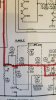
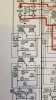
Anyways, Retrovert, I found your original post from which you quoted. Sounds like I should be using metal film resistors and polystyrene caps on perf board. Do I use 1/2w resisters? And how do I determine what voltage caps I need? Fortunately, the Scott schematic has the PEC schematics built in, and has the basic information but not wattage and voltage. I've attached photos.
Many thanks as always. As a side note, the Scott manual refers to PECs as "Packaged Electronic Circuits" rather than printed. Not sure if there's a difference, or is it just terminology?
My best,
Saul
I'll test all four PECs (two in the scratch, two in the phono) using the trashcan method. Will report findings.
Anyways, Retrovert, I found your original post from which you quoted. Sounds like I should be using metal film resistors and polystyrene caps on perf board. Do I use 1/2w resisters? And how do I determine what voltage caps I need? Fortunately, the Scott schematic has the PEC schematics built in, and has the basic information but not wattage and voltage. I've attached photos.
Many thanks as always. As a side note, the Scott manual refers to PECs as "Packaged Electronic Circuits" rather than printed. Not sure if there's a difference, or is it just terminology?
My best,
Saul
Attachments

trainbuftony
Electron Herder
Quarter watt resistors should work fine, i use half watt because i dont stock 1/4 watt Rs. For the caps, mesure the voltage on the plate of the subsequent tube And order caps well above that value. If you measure 200v, use a 350v cap.
Hello 6DZ7 and everyone else.
Thanks for that good suggestion. I retouched the solder on the pins, but no change.
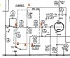
I've attached the PEC-299 schematic with the pinout as it appears in my amp marked in red numbers, for your reference.
As far as I can tell, none of the resistors are showing open, as testing resistance between any two pins always shows either a number or OL, never 0. However, I'm not really certain how to test any isolated components, since everything seems to be linked inside of the PEC. For instance, although there is only one cap between pins 6 and 2, pin 6 is also connected to R117, R118, C114, and C113. Would the results of testing between pins 6 and 2 be influenced by the connection of pin six to other resistors and capacitors? I was thinking this must be true because even after unsoldering the leads, testing between pins 5(b) and 4 yields a steadily rising reading (as though a capacitor were involved), rather than the stable reading I would expect from a single resistor. I'm confused! 6DZ7, are there any specific measurements on the PEC that you recommend me doing that would help me analyze what inside the PEC may be acting up?
Also, as I was trying to track down this mystery, I noticed a second (related?) mystery. Between the tape in/out switch and the selector switch there are, in each channel, a 180pf mica cap and a 100k resistor attached in parallel (this is c10, r15/ c110, r115 on the schematic, which is attached earlier in this thread). My scope shows that, when a 1000hz sine wave is played through the extra input, the readings for each channel are identical before this cap/resistor pair, but are diminished unequally after. That is, both waveforms decrease in amplitude, but one more than the other. I tested the resistors, and both test at ~96k. Now I hear that mica caps rarely if ever go bad, but it seems to me the caps must be bad. I'm thinking I will replace both, just so I know they are both the same. Unless anyone more knowledgeable than me has a better suggestion!
Lastly, I'm confused about capacitor units on the PEC insert for the schematic, since I can't look at the actual capacitors and check against the schematic. Inside the PEC schematic, we have one 330 cap, one 62 cap, and .0012 cap. I assume the .0012 cap is uf. What units are we talking about here for 330 and 62? I would guess pf, but the only film caps that mouser sells with a 300pf rating are these weird kemet caps. I've never used any like this, so in the event I have to replace the PECs, I want to make sure I'm getting the right thing. https://www.mouser.com/ProductDetail/KEMET/PHE450KK3330JR17?qs=MdJgNetHbflrVCTFfU0dlg==
EDIT: Mouser does have ceramic disc caps in the appropriate rating. https://www.mouser.com/ProductDetai...331K20Y5PL63L6R?qs=HhInGfH%2BevjD2GCBxkM1ZA==
Thanks so much for helping clear up my confusion, as ever.
Saul
Thanks for that good suggestion. I retouched the solder on the pins, but no change.
I've attached the PEC-299 schematic with the pinout as it appears in my amp marked in red numbers, for your reference.
As far as I can tell, none of the resistors are showing open, as testing resistance between any two pins always shows either a number or OL, never 0. However, I'm not really certain how to test any isolated components, since everything seems to be linked inside of the PEC. For instance, although there is only one cap between pins 6 and 2, pin 6 is also connected to R117, R118, C114, and C113. Would the results of testing between pins 6 and 2 be influenced by the connection of pin six to other resistors and capacitors? I was thinking this must be true because even after unsoldering the leads, testing between pins 5(b) and 4 yields a steadily rising reading (as though a capacitor were involved), rather than the stable reading I would expect from a single resistor. I'm confused! 6DZ7, are there any specific measurements on the PEC that you recommend me doing that would help me analyze what inside the PEC may be acting up?
Also, as I was trying to track down this mystery, I noticed a second (related?) mystery. Between the tape in/out switch and the selector switch there are, in each channel, a 180pf mica cap and a 100k resistor attached in parallel (this is c10, r15/ c110, r115 on the schematic, which is attached earlier in this thread). My scope shows that, when a 1000hz sine wave is played through the extra input, the readings for each channel are identical before this cap/resistor pair, but are diminished unequally after. That is, both waveforms decrease in amplitude, but one more than the other. I tested the resistors, and both test at ~96k. Now I hear that mica caps rarely if ever go bad, but it seems to me the caps must be bad. I'm thinking I will replace both, just so I know they are both the same. Unless anyone more knowledgeable than me has a better suggestion!
Lastly, I'm confused about capacitor units on the PEC insert for the schematic, since I can't look at the actual capacitors and check against the schematic. Inside the PEC schematic, we have one 330 cap, one 62 cap, and .0012 cap. I assume the .0012 cap is uf. What units are we talking about here for 330 and 62? I would guess pf, but the only film caps that mouser sells with a 300pf rating are these weird kemet caps. I've never used any like this, so in the event I have to replace the PECs, I want to make sure I'm getting the right thing. https://www.mouser.com/ProductDetail/KEMET/PHE450KK3330JR17?qs=MdJgNetHbflrVCTFfU0dlg==
EDIT: Mouser does have ceramic disc caps in the appropriate rating. https://www.mouser.com/ProductDetai...331K20Y5PL63L6R?qs=HhInGfH%2BevjD2GCBxkM1ZA==
Thanks so much for helping clear up my confusion, as ever.
Saul
Attachments
Retrovert
Addicted Member
Hello to all. Many thanks for this invaluable information. AK always amazes me, y'all are such a great resource.
You're welcome.
I'll test all four PECs (two in the scratch, two in the phono) using the trashcan method. Will report findings.
Outstanding. That's the only PEC test which matters. Works every time!
Anyways, Retrovert, I found your original post from which you quoted. Sounds like I should be using metal film resistors and polystyrene caps on perf board. Do I use 1/2w resisters? And how do I determine what voltage caps I need? Fortunately, the Scott schematic has the PEC schematics built in, and has the basic information but not wattage and voltage. I've attached photos.
Metal film has very low noise, particularly compared to the original carbon composition, and it does not have the Vcr problem, hence no non-linear distortion. Hafler wrote of his difficulty in finding low-noise cracked carbon resistors (an early technology for carbon film, another less desirable resistor) for the Dynaco PAS and how a change in the resistors increased waterfall noise and delayed shipment.
I would not use polystyrene capacitors. I think you meant polypropylene, as this is the technology to use. PS had the advantage of temperature stability, but were easily damaged in soldering, particularly wave, which pretty much was the death knell for it as a capacitor technology.
Many thanks as always. As a side note, the Scott manual refers to PECs as "Packaged Electronic Circuits" rather than printed. Not sure if there's a difference, or is it just terminology?
The name "Packaged Electronic Circuits" aka "PEC" became the generic term for what Centralab originally named the "Printed Electronic Circuit" aka "PEC". The nomenclature change was to highlight the fact that more complex circuits could be fabbed on the ceramic substrate, and it was better to sell the concept as arbitrary circuitry. So the name one uses depends upon the timeframe, but they're all really the same.
But the naming becomes messier. The descriptive name could not be trademarked, as printed circuit was already known, as was a packaged circuit. So Centralab switched to using the trademarked name "Couplate" and Sprague adopted the trademarked name "Bulplate", while Aerovox continued with the generic "PEC" since engineers were calling them PECs anyway. But engineers weren't calling them Couplates or Bulplates, as these were new and silly names, and the articles and design documents referred to PECs. So the only use of Couplate or Bulplate was in catalogs from their respective vendors.
You can call PECs anything you like, as long as you don't call them late to the trashcan.
Retrovert
Addicted Member
Lastly, I'm confused about capacitor units on the PEC insert for the schematic, since I can't look at the actual capacitors and check against the schematic. Inside the PEC schematic, we have one 330 cap, one 62 cap, and .0012 cap. I assume the .0012 cap is uf. What units are we talking about here for 330 and 62? I would guess pf, but the only film caps that mouser sells with a 300pf rating are these weird kemet caps. I've never used any like this, so in the event I have to replace the PECs, I want to make sure I'm getting the right thing.
Unspecified units for the PEC, like other capacitors of the day, are usually mmF aka pF.
Just checked. Conventional polypropylene film is available from Mouser in 330 pF, 5% for $1, Kemet, standard axial. See:
I narrowed with polypropylene, then axial lead.
EDIT: Mouser does have ceramic disc caps in the appropriate rating.
Suggest not placing any ceramics in the audio path unless you know the properties are suitable. BaTiO3 is not, and many of the monolithics are not. The additional cost for film is small and worth it.
Retrovert
Addicted Member
Quarter watt resistors should work fine, i use half watt because i dont stock 1/4 watt Rs.
Yup.
I prefer the higher-wattage resistors because they're much easier to handle, easier to read, run cooler, have lower noise
Incremental cost is small.
(TWO YEARS AND A PANDEMIC LATER).
Hello audio mentors. Finally had a little bit of free time and am back on the old Scott, which despite my best efforts is still having issues--and I would greatly appreciate any advice on oscilloscope readings that are confusing me.
Where we left off: I've replaced all the capacitors, the ss rectifier, and a few of the tubes which were testing poorly. I fixed the above-mentioned burning resistor with a new rectifier tube. I've still got a channel imbalance which isn't effected by moving the tubes from one channel to the other, and I'm trying to make sense of it using my oscilloscope and a lot of audiokarma reading, but am getting stuck.
I thought I'd start with one piece of information that may be of help in helping me to help the amp. When nothing is plugged into any of the inputs on the amp, I get the attached scope readings at the speaker terminals (first two pictures). (I've inverted channel b on the scope in these pictures.) The first one is with the volume turned all the way down. The second, with the volume turned all the way up. Again, there's no signal going into the amp. This is a 60hz wave. Adjusting the volume amplifies the wave in the left channel substantially more than the right.
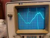
When I input a square wave, I get the reading in the final picture. I know there's some ringing--and I think this might be caused by my "signal generator" AKA cell phone. But the duplicate waves as well as the slope of that waveform (that's the left channel that is acting up) is leaving me scratching my head. So I guess I'm wondering if someone could try to help me troubleshoot. I can and am happy to take further readings on the scope or my DMM--whatever is necessary! Just feeling stuck, and seeking out advice.
Kind thanks.
Humbly yours,
Saul
Hello audio mentors. Finally had a little bit of free time and am back on the old Scott, which despite my best efforts is still having issues--and I would greatly appreciate any advice on oscilloscope readings that are confusing me.
Where we left off: I've replaced all the capacitors, the ss rectifier, and a few of the tubes which were testing poorly. I fixed the above-mentioned burning resistor with a new rectifier tube. I've still got a channel imbalance which isn't effected by moving the tubes from one channel to the other, and I'm trying to make sense of it using my oscilloscope and a lot of audiokarma reading, but am getting stuck.
I thought I'd start with one piece of information that may be of help in helping me to help the amp. When nothing is plugged into any of the inputs on the amp, I get the attached scope readings at the speaker terminals (first two pictures). (I've inverted channel b on the scope in these pictures.) The first one is with the volume turned all the way down. The second, with the volume turned all the way up. Again, there's no signal going into the amp. This is a 60hz wave. Adjusting the volume amplifies the wave in the left channel substantially more than the right.
When I input a square wave, I get the reading in the final picture. I know there's some ringing--and I think this might be caused by my "signal generator" AKA cell phone. But the duplicate waves as well as the slope of that waveform (that's the left channel that is acting up) is leaving me scratching my head. So I guess I'm wondering if someone could try to help me troubleshoot. I can and am happy to take further readings on the scope or my DMM--whatever is necessary! Just feeling stuck, and seeking out advice.
Kind thanks.
Humbly yours,
Saul
Attachments

![PXL_20220307_232642873[17575].jpg](/forums/data/attachments/2380/2380070-fe1813d02eba6635e1222f3ba0d0993c.jpg?hash=_hgT0C66Zj)

60hz with volume full up and nothing connected to the inputs isn't uncommon. Use a shorting plug on the input and see if that stops. Also you probably want to put the bottom on, and make sure all tube shields are in place to get a really good idea of exactly what its doing. Related, whats the v/div setting on the scope for all of this?
working from this schematic just for reference. If this doesn't match yours, let us know
hhscott.com/pdf/fs/LK72B.JPG
Specific to the hookup here, the "common" terminal is not connected to ground, and your scope can't be either. Scope negative to the 4 ohm terminal, scope + to the 16 ohm. Use a 4 ohm dummy load across the same terminals and let us know what you get. If its connected in a different manner you're going to see some strange things on the scope that don't make sense.
working from this schematic just for reference. If this doesn't match yours, let us know
hhscott.com/pdf/fs/LK72B.JPG
Specific to the hookup here, the "common" terminal is not connected to ground, and your scope can't be either. Scope negative to the 4 ohm terminal, scope + to the 16 ohm. Use a 4 ohm dummy load across the same terminals and let us know what you get. If its connected in a different manner you're going to see some strange things on the scope that don't make sense.
Gadget,
Thanks for the reply!
Before I go any further with answering your questions, I do want to make sure I understand you correctly and am doing this right. The way I have it set up currently is that the amp is set up for 8ohm speakers--the red and green wires coming the chassis are hooked into the 8ohm terminals on the back of the amp. The dummy loads--one 8ohm 100w resistor for each channel--are hooked up the way I would hook up speakers--to the "H" and "O" terminals, as they are marked on the amp. I had the scope probe positive hooked up to the "H" side of the resistor, and the negative (ground?) hooked up to the chassis, as I would have if testing inside the amp. Is this... not the way to go about it? Thanks for your help--I'll take all I can get!
Thanks for the reply!
Before I go any further with answering your questions, I do want to make sure I understand you correctly and am doing this right. The way I have it set up currently is that the amp is set up for 8ohm speakers--the red and green wires coming the chassis are hooked into the 8ohm terminals on the back of the amp. The dummy loads--one 8ohm 100w resistor for each channel--are hooked up the way I would hook up speakers--to the "H" and "O" terminals, as they are marked on the amp. I had the scope probe positive hooked up to the "H" side of the resistor, and the negative (ground?) hooked up to the chassis, as I would have if testing inside the amp. Is this... not the way to go about it? Thanks for your help--I'll take all I can get!
If you had the scope - connected to chassis, you're fine. Just can't connect scope - to the O terminal like you were reading directly across the speaker load.
just be aware that the voltage measured on the scope doesn't match whats being sent to the speaker though. Not a problem just for signal tracing but don't use it for any sort of power calculations.
just be aware that the voltage measured on the scope doesn't match whats being sent to the speaker though. Not a problem just for signal tracing but don't use it for any sort of power calculations.
Thanks Gadget--very helpful.
I was getting so confused with the scope readings that I decided to go back and start somewhere familiar to me to track down this imbalance--voltage! I measured all the voltage test points as indicated in the schematic (I think the one you posted is correct gadget, but the link you sent isn't working). I've attached the schematic here with my measurements. (I'm not sure if this was the best way to share the info, so let me know if a chart or something would be more useful). The places I noticed larger variations from the noted values were V102-A, and V3. V103 is also a bit off, but less so than V3. (v103 and v3 are 6u8s). I'm still shaky on my phase inverter knowledge, so I'm not totally sure what could be causing these readings or how to fix them. Switching the 6u8s does not change the readings--they stay in the same location, don't move with the tube. Would I be right in thinking a resistor might be off somewhere? Or perhaps a short or something is drawing current where it shouldn't be? I already replaced R35/135 and R39/139, and I'm running the amp at 117v from a variac.
Any ideas where to go from here?
Many thanks as always.
I was getting so confused with the scope readings that I decided to go back and start somewhere familiar to me to track down this imbalance--voltage! I measured all the voltage test points as indicated in the schematic (I think the one you posted is correct gadget, but the link you sent isn't working). I've attached the schematic here with my measurements. (I'm not sure if this was the best way to share the info, so let me know if a chart or something would be more useful). The places I noticed larger variations from the noted values were V102-A, and V3. V103 is also a bit off, but less so than V3. (v103 and v3 are 6u8s). I'm still shaky on my phase inverter knowledge, so I'm not totally sure what could be causing these readings or how to fix them. Switching the 6u8s does not change the readings--they stay in the same location, don't move with the tube. Would I be right in thinking a resistor might be off somewhere? Or perhaps a short or something is drawing current where it shouldn't be? I already replaced R35/135 and R39/139, and I'm running the amp at 117v from a variac.
Any ideas where to go from here?
Many thanks as always.
Attachments
yeah the site seems to have gone down later in the day after I posted that link. Not sure whats going on there.
Anyway, voltages in the output stage look pretty good overall. If you still get 60hz noise with the volume all the way down that eliminates a lot of stuff. First suspect at this point would be a heater-cathode leak in the 6BL8 tubes. Happen to have another set? If not, just pull them and see if it stops.
Anyway, voltages in the output stage look pretty good overall. If you still get 60hz noise with the volume all the way down that eliminates a lot of stuff. First suspect at this point would be a heater-cathode leak in the 6BL8 tubes. Happen to have another set? If not, just pull them and see if it stops.
Thanks Gadget--very helpful.
I was getting so confused with the scope readings that I decided to go back and start somewhere familiar to me to track down this imbalance--voltage! I measured all the voltage test points as indicated in the schematic (I think the one you posted is correct gadget, but the link you sent isn't working). I've attached the schematic here with my measurements. (I'm not sure if this was the best way to share the info, so let me know if a chart or something would be more useful). The places I noticed larger variations from the noted values were V102-A, and V3. V103 is also a bit off, but less so than V3. (v103 and v3 are 6u8s). I'm still shaky on my phase inverter knowledge, so I'm not totally sure what could be causing these readings or how to fix them. Switching the 6u8s does not change the readings--they stay in the same location, don't move with the tube. Would I be right in thinking a resistor might be off somewhere? Or perhaps a short or something is drawing current where it shouldn't be? I already replaced R35/135 and R39/139, and I'm running the amp at 117v from a variac.
Any ideas where to go from here?
Many thanks as always.
You might want pay special attention to C125 and C128 on the channel with the low voltage readings.
They're either ceramic disc or silver mica caps, and dirt cheap to replace if questionable.
Gadget: the 60hz noise does vary with the volume. With the volume all the way down, there is almost no noise (maybe .005v). With the volume and bass all the way up, there is about .4v of a 60hz hum. With bass at center and volume all the way up, there is about .08v hum. I haven't tried this on speakers yet and I'm not familiar enough with these scope readings to know if this is going to be audible. Pulling the 6BL8 tubes does get rid of the hum (except for about .01v of some 120hz hum), but since the 60hz hum varies with volume, I suspect it originates before the 6BL8s?
When I play a sine wave through the amp and measure the signal at the speaker terminals, the sine wave appears to be "riding" the 60hz hum, if that makes sense--the whole sine wave undulates. Is somebody able to explain what's happening there to me?
Pablodeux: thanks for that tip. I'll take a look at those. C125 appears to be a silver mica, and C128 a ceramic disc. Probably don't have replacements sitting around anywhere, but I will check!
As for the channel imbalance, it seems to have "worked itself out" is all I can say. I keep buying these cheap (but recommended) scope probes on Amazon, and honestly I think they may be causing me grief. Now I'm just using a single probe and going back and forth between the channels rather than using two probes, and as of now, that seems to have "fixed" the channel imbalance at present--I still have to put the balance pot slightly off center to get the output amplitudes to be equal, but not by much. Maybe getting the voltages right will fix this?
When I play a sine wave through the amp and measure the signal at the speaker terminals, the sine wave appears to be "riding" the 60hz hum, if that makes sense--the whole sine wave undulates. Is somebody able to explain what's happening there to me?
Pablodeux: thanks for that tip. I'll take a look at those. C125 appears to be a silver mica, and C128 a ceramic disc. Probably don't have replacements sitting around anywhere, but I will check!
As for the channel imbalance, it seems to have "worked itself out" is all I can say. I keep buying these cheap (but recommended) scope probes on Amazon, and honestly I think they may be causing me grief. Now I'm just using a single probe and going back and forth between the channels rather than using two probes, and as of now, that seems to have "fixed" the channel imbalance at present--I still have to put the balance pot slightly off center to get the output amplitudes to be equal, but not by much. Maybe getting the voltages right will fix this?
yeah if its quiet with the 6bl8 in and the volume down, its before the volume control. That wasn't clear from the prior post.
The 60 hz modulated wave is pretty typical of what you'll see when its got a lot of hum. You're just seeing two frequencies being amplified at the same time. Should watch what happens when playing music, its a complete mess on the scope.
Is this with all the shields, bottom, etc installed?
The 60 hz modulated wave is pretty typical of what you'll see when its got a lot of hum. You're just seeing two frequencies being amplified at the same time. Should watch what happens when playing music, its a complete mess on the scope.
Is this with all the shields, bottom, etc installed?
Hi all. I had a little time to work on the amp. Here's what I've got now:
Gadget: the hum still exists with all the shields, bottom, etc. One thing that keeps confusing me about the scope is that when it's set to low volts/div, the probes read a 60hz modulated wave even when the probes aren't attached to anything but the scope. From what I'm reading this is because noise from the mains is getting picked up ambiently from the probes. Is that right? It's still true even when the probes are grounded to the chassis of the amp. Anyway, it makes it difficult for me to track the 60hz hum in the amp, since there's always one floating on the scope. Any tips there?
Also, the channel imbalance is in fact still present even with better matched probes. I tracked it to the volume pot. I pulled the pot and indeed resistance varies considerably (20k ohms in some places) between the two gangs. There are also places on the track where the carbon seems worn away and my DMM reads open. I tried cleaning it with deoxit, but nothing changes, and there doesn't seem to be a good way to adjust one wiper relative to the other--they are pinned pretty sturdily to the arbor.
So, I'm thinking I need a new volume pot. I've already moved the on/off switch to a toggle on the rear of the chassis, so I'm in need of one of those elusive 500k center tapped dual gang pots (though without the switch). I know there's that guy on the auction site, but besides being outrageously expensive, it sounds like he's a bit dodgy. I tried contacting Mark Oppat but haven't heard back yet. Anybody got one they'd be willing to sell me? Or any leads on new or NOS? I've searched the forums and found this question come up, but nobody seems to have found a reliable source. I posted to Bartertown parts WTB also.
Thanks kindly for all the help. Hope your Wednesdays are going well.
Best,
Saul
Gadget: the hum still exists with all the shields, bottom, etc. One thing that keeps confusing me about the scope is that when it's set to low volts/div, the probes read a 60hz modulated wave even when the probes aren't attached to anything but the scope. From what I'm reading this is because noise from the mains is getting picked up ambiently from the probes. Is that right? It's still true even when the probes are grounded to the chassis of the amp. Anyway, it makes it difficult for me to track the 60hz hum in the amp, since there's always one floating on the scope. Any tips there?
Also, the channel imbalance is in fact still present even with better matched probes. I tracked it to the volume pot. I pulled the pot and indeed resistance varies considerably (20k ohms in some places) between the two gangs. There are also places on the track where the carbon seems worn away and my DMM reads open. I tried cleaning it with deoxit, but nothing changes, and there doesn't seem to be a good way to adjust one wiper relative to the other--they are pinned pretty sturdily to the arbor.
So, I'm thinking I need a new volume pot. I've already moved the on/off switch to a toggle on the rear of the chassis, so I'm in need of one of those elusive 500k center tapped dual gang pots (though without the switch). I know there's that guy on the auction site, but besides being outrageously expensive, it sounds like he's a bit dodgy. I tried contacting Mark Oppat but haven't heard back yet. Anybody got one they'd be willing to sell me? Or any leads on new or NOS? I've searched the forums and found this question come up, but nobody seems to have found a reliable source. I posted to Bartertown parts WTB also.
Thanks kindly for all the help. Hope your Wednesdays are going well.
Best,
Saul