

You are using an out of date browser. It may not display this or other websites correctly.
You should upgrade or use an alternative browser.
You should upgrade or use an alternative browser.
HH Scott LK72B, a dirty dog!
- Thread starter spxer
- Start date

at full voltage with diodes you're probably exceeding the voltage rating on the caps. Hook a voltmeter up and verify what the B+ actually is, and make sure its not beyond the cap limit. Watch the ones further down the line too, with no tubes they will see a lot more voltage than they normally would.

and I'm not totally clear about why you're using the diodes (not doubting your approach) but I have always read that you should be using an incandescent high wattage bulb for a DBT. 300W if you can get it
well that would do it. What diodes did you use ? The 5AR4 is rated for something like 1500 volts, any solid state ought to at least match that. A pair of 1n4007 in series will get you 2kv. Takes 4 total but they are cheap enough.
thats also the saving grace of the dim bulb, it will limit current below the point where anything bad can really happen.
thats also the saving grace of the dim bulb, it will limit current below the point where anything bad can really happen.

spxer
Active Member
I have ordered parts and have some in. I am not sure where the CL-80 inrush thermister should go. The Amphenol data sheet shows it in the DC line. Forum searches here suggest in the incoming AC line. Where is the best location for the this amp?
Also, there is the suggestion one should run a resistor in line with the Silicon Bridge. What size resistor?
Also, there is the suggestion one should run a resistor in line with the Silicon Bridge. What size resistor?

drew_t
Well-Known Member
Put the CL-80 in one of the AC legs right past the cord’s entry point into the chassis, wherever you can fit it in and have some air space around it - it gets hot. Not sure if this has already been mentioned, but replacing the cap that goes across the AC lines (C206) with a modern X1/Y2 safety cap is also a good idea.
Regarding resistors after the bridge rectifier, some experimentation may be needed. The attached diagram shows the expected voltages before and after the existing 33 ohm resistor. Once you have the silicon bridge and the CL-80 installed, take some measurements.
Regarding resistors after the bridge rectifier, some experimentation may be needed. The attached diagram shows the expected voltages before and after the existing 33 ohm resistor. Once you have the silicon bridge and the CL-80 installed, take some measurements.
Attachments
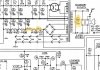


Can someone tell me why V2 and V102, which are the left and right channel pre-amp12AX7 tubes, would be wired differently? The schematic shows them both wired the same. The assembly manual does not. The amp in question is wired as in the manual.
View attachment 2719939
View attachment 2719947
I noticed this a few years back when I was working on my LK72B.
After studying it for a while, I realized that since the 12AX7 has 2 identical triode sections housed in the same glass envelope, it doesn't make any difference to the audio signal which section sees the signal first.
I think the industrial engineering types at Scott who create the assembly instructions, realized it was simpler to wire them in reverse order for each channel due to the relationship between the terminal strips and the tube socket pin numbering.
It doesn't look like the folks who update the schematics thought it was worthy of the effort and expense required to update the drawing to reflect the change in the way the amplifiers were actually being made.
spxer
Active Member
Thanks, gadget73 and Pablodeux. I get it now. 2 tubes in one. So if I change the numbering on the schematic. It should are all correspond.
Sent me into a tizzy. I thought I might have to rewire the amp. I have been just replacing part for part, but doing some checking along the way.
Sent me into a tizzy. I thought I might have to rewire the amp. I have been just replacing part for part, but doing some checking along the way.


