• The move to the new server is done. There are some software and database maintenance updates in process. This has us passing the hat around to help out. We appreciate any donations. Seriously, even a dollar helps. The payment page may be found here - https://www.audiokarma.org/support.html

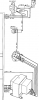
HK 330b chassis measuring 120 volts

bubbletrou

New Member
Hi all, thanks to @dlucy 's many incredible threads on the topic, I have begun the process of restoring a non-functioning 330b that I purchased for cheap. I have replaced the majority of the components on the main amp board and gotten it working with one caveat: the chassis seems to be 'hot'. With a multimeter, I see 120 volts at the chassis when the power switch is off and switching the power cord polarity gives me 120 volts at the chassis when the power switch is on.

Looking at the schematics and the pictures on other threads, I have the 'MV' version of variant #3 (meaning that I have the voltage selector switch, capacitor and resistor to chassis from the power cord, etc)

Any thoughts/things to try?

Thanks for all for the help!
 
Register to hide this ad
In guitar amps they used to put a noise suppression cap from the line to ground. It became known as the "Death Cap" because if it leaked or shorted you could get AC on the chassis and it became a shock hazard. Is it possible there's something like this happening in your amp? That's where my investigation would start. Good luck.
 
A moden DMM has a very high impedance, and even a small amount of leakage (and there will be leakage with any amount of R or C from line to ground) can show up as a frightening high voltage. The standard way to measure leakage and determine if it is at a safe level is this:
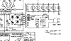
Annotation 2020-05-18 125011.png
Alternately, you can grab a 4 watt *incandescent* night light bulb and connect it between the receiver chassis and the ground terminal of the power outlet. If it glows at all, you have a leakage problem.
 
A moden DMM has a very high impedance, and even a small amount of leakage (and there will be leakage with any amount of R or C from line to ground) can show up as a frightening high voltage. The standard way to measure leakage and determine if it is at a safe level is this:
View attachment 1870523
Alternately, you can grab a 4 watt *incandescent* night light bulb and connect it between the receiver chassis and the ground terminal of the power outlet. If it glows at all, you have a leakage problem.

Makes sense to me. I get a pretty nice shock when I touch the knobs / chassis, so something is definitely wrong. I'm wondering if there is something going on with the line to ground capacitor like @JohnT123 suggested above.
 
Yeah, you shouldn't get a shock. I don't see your configuration in the 330a/b schematics I have, can you post a diagram of your config?
 
Is that **really** a 2.2 ohm resistor, or did they forget to print the 'M'?
A 0.01 uF cap should give you less than 0.5 mA of 'leakage'. With the unit unplugged but the power switch on, measure the resistance between either prong of the power plug and the receiver chassis. Should be >1 meg.
 
Is that **really** a 2.2 ohm resistor, or did they forget to print the 'M'?
A 0.01 uF cap should give you less than 0.5 mA of 'leakage'. With the unit unplugged but the power switch on, measure the resistance between either prong of the power plug and the receiver chassis. Should be >1 meg.
I noticed the missing 'M' as well...the schematic for the other version has an M and testing either prong to chassis with a multimeter gives ~2.2M, so I am thinking that it is a typo.
 
I see 120 volts at the chassis when the power switch is off and switching the power cord polarity gives me 120 volts at the chassis when the power switch is on.

Aside:
Please explain: Is this component failure or a human cause of mistake after the factory? I should think if comp. failure a fuse should blow.
 
Nothing seems grossly wrong. With a reading of 2.2 megs, the capacitor is not excessively leaky and the transformer does not have a winding to frame short. Try measuring the leakage with the standard test circuit - what you have may be normal and you are just highly sensitive to small currents.
 
...I should think if comp. failure a fuse should blow.

Not if it is present via a high impedance path, unless the fuse is very small.

Someone mentioned a 2.2M resistor. If that is the path then it would allow just 55uA at 120V. Not enough to blow a typical power fuse.
 
Thank you all for the replies. The shock (tingle?) I get from touching the chassis is roughly the same as the feeling you get from licking a 9V battery.

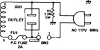
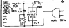
I took a look at where the AC lines are and everything looked ok as far as I could tell. Does someone with more of an EE understanding/background have any thoughts as to why the AC section of the MV vs the RV variants looks different (no cap on the RV, resistor on the switched vs non-switched side, etc)? Just for fun, I may try replacing the capacitor to see if things behave any differently.

RV:
RV.PNG

MV:
MV.PNG
 
Thanks @whoaru99


Geezzzz initially I assumed you were getting hit with more substantial current.
Haha I guess I initially overstated the severity of the issue...you definitely feel it and it does not feel pleasant, but it is nothing too serious. Just doesn't seem like proper operation to me.
 
Does someone with more of an EE understanding/background have any thoughts as to why the AC section of the MV vs the RV variants looks different (no cap on the RV, resistor on the switched vs non-switched side, etc)?
Requirements of the certifying agency. UL usually wants something different than CSA which is different than ETL, which is different than CE, which is different than TUV, etc.
 
That area where the AC cord comes in, is carried to the fuses and the switched/unswitched plugs is tight and often has wear problems. One thing to check would be to see if any of those AC-carrying wires where shorting to anything else.
Path of least resistance
 
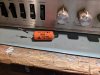
I removed the line to ground capacitor just to see if it made a difference and now I don't get a shock when touching the chassis. I will try replacing it and seeing if things stay fixed

IMG_20200519_212859.jpg
 
Last edited:
Back
Top Bottom