• The move to the new server is done. There are some software and database maintenance updates in process. This has us passing the hat around to help out. We appreciate any donations. Seriously, even a dollar helps. The payment page may be found here - https://www.audiokarma.org/support.html

HK A500 Output Tube Experiments (Again)

TriodeLuvr

So many electrons, so little time!
Subscriber
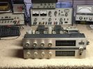
I pulled my A500 out of storage today in anticipation of it being the next project. I'll be stripping off the iron for a new build, and the various options for output tubes are my primary consideration. I do have a NOS quad of the original tube type (7355), as well as several quads of used tubes. However, I'd like to eventually sell those and use the proceeds to fund other projects. 6L6 variants like the 6L6GB or 6P3S-E are another option, but previous experiments in the circuit have indicated that they don't perform quite as well as the original type, probably due to the low-ish primary impedance of the output transformers. Another member here recently built an amp from the A500 output transformers using PPP 6V6s. That's a better match for the transformers, and it appears to have worked out well. However, I'm not overly excited by the prospect of needing eight reasonably well-matched output tubes for one stereo amplifier.

At this point, I'm also still considering the EL34 for this build, something that's been discussed here before. I've always considered this tube to be the most similar analog to the 7355 in terms of operating conditions and optimum plate load. The 1.5A heaters are a significant problem of course, but I have two A500 power transformers now and am strongly considering building monoblocks. That resolves all the issues regarding heater current, because each transformer would see slightly less heater draw with two EL34 in mono than a single transformer does with four 7355 for stereo.

To gather more data, I rewired one channel of the A500 to receive a pair of EL34. No output tubes are installed in the other channel, and the grid circuit has been modified so fixed bias can be applied from my bench supply. Each cathode is grounded through a 10Ω resistor for monitoring. The driver tube filaments that were previously powered by output cathode current are now connected to the main 6.3V heater wiring. So far, the results look pretty good.

EDIT: Data previously posted here has been deleted due to an issue discovered in the amplifier that was affecting results. Revised data has been posted further down the thread.

Jack
 
Last edited:
Register to hide this ad
What are your power output goals? Sounds like with your Cornwalls, you have plenty of power if nominal power output is 30~40W/ch.
 
I did a quick and dirty test with my Bogen DS-225 using 6L6, 7868, and EL34 tubes as subs for the 7355, and the EL34 performed most like the 7355. Somewhere I made notes on it but thats what I remember without finding the specifics.

I don't remember if I tried the 6P3S or 6P3SE tubes, I tried it with original metal 6L6 tubes. I didn't have the usually-suggested 5881 and I figured a regular 6L6 would perform about the same. The Bogen's power supply is right within 6L6/6L6G voltage specs.
 
What are your power output goals? Sounds like with your Cornwalls, you have plenty of power if nominal power output is 30~40W/ch.
I'm not using Cornwalls. Gave them the boot after a couple weeks of listening, insufficient bass. They were the second pair I've tried at my house (should have learned my lesson the first time). Speakers are DIY, built from a custom LEAP design generated for me by Madisound 20 years ago. They're ported, tuned to slightly above 20Hz, sensitivity estimated at 95dB. They produce a lot of bass you can only feel, not hear, and it's very tight with most amps.

Power goals? Heck I don't know, whatever I can get. :) Seriously, I just don't want less than the stock amplifier. I believe the factory configuration with 7355s produces 26W to 27W. The EL34 does better than those in my tests because I've modified the configuration to fixed bias. Also, local line voltage and the fact I'm only running one pair of tubes conspire to increase B+ by 30V or so. I'm pretty sure the 7355 would perform similarly to the EL34 in this situation. The 6L6 types are designed for higher load Z, so they fall behind. The 6L6GB and 6P3S-E don't meet the factory output spec in this amp in its original configuration with cathode bias and +370V B+. That was one of the first things I tried several years ago.

Jack
 
Last edited:
Similar transformers in the TA-5000 measured 4100 Ohms with an 8 Ohm load. Had a low-Q resonance at 120 KHz that shouldn't be hard to deal with.
 
I have just discovered that the impedance selection jumper in the A500 is intermittent. The previously posted operating data is now all in question, and I have deleted it. I'm running new tests and will repost shortly. Sorry about this.

Jack
 
Last edited:
Here are my measurements from about a year ago:

A500 Output Transformer # FT3824638

Unloaded:
16 Ohm 10v/0.679v (3.471K)
8 Ohm 10v/0.478v (3.497K)
4 Ohm 10v/0.339v (3.480K)

Loaded with corresponding resistive load
16 Ohm 10v/0.6v (4.445K)
8 Ohm 10v/0.41v (4.759K)
4 Ohm 10v/0.289v (4.788K)

Quote Reply
 
I've completed the new measurements now, and these are all continuous power numbers. The short-term bursts I used earlier don't produce as much difference now that the loading is nailed down, so no reason to include them here.

6P3S-E (1kHz) : 27.5W

6L6GB (1kHz) : 33W

EL34 (1kHz) : 36W
EL34 (1kHz) : 36W

Just to reiterate, these results are in an A500 amplifier that is applying more plate and screen voltage than stock, is fixed bias, has a lower impedance power supply than the factory unit, and only one channel is operating. Looking this over, the difference between the EL34 and 6L6 is not too significant under these conditions. I have a couple dozen of the latter, but only a few EL34, so that's probably the direction I'm headed with this build.

Jack
 
I’m watching because I was also thinking about extracting the iron off of my A500 and building some kind of hot rod. I was thinking of using the same basic amplifier circuit with the short loop pos feedback inside a global neg feedback loop, as a nod to the original design.
 
Had a low-Q resonance at 120 KHz that shouldn't be hard to deal with.
These are also about 120kHz. That's the ringing frequency when the amplifier is driven with a 10kHz square wave. A quick sine sweep with a couple watts output is flat from below 10Hz to about 50kHz. These are good transformers.
I’m watching because I was also thinking about extracting the iron off of my A500 and building some kind of hot rod. I was thinking of using the same basic amplifier circuit with the short loop pos feedback inside a global neg feedback loop, as a nod to the original design.
This amp was my reintroduction to tube audio more than 25 years ago. It cost me all of $20. I stripped out the tone circuitry at that time and had thought about cutting a new faceplate. However, I want a cleaner looking chassis of my own design. This one would also need all the old wiring stripped out and replaced because it's greening, just like my Cit V. I'd rather just start from scratch.

HK used nested positive feedback to create the necessary gain. RCA also did this in at least one of the designs published in the back of their tube manuals. Despite having only a 12AX7 feeding a 12AU7 cathodyne, driver gain is about 340. Pretty remarkable. This amp was very open and detailed when it was working, so I might also copy the original circuit. In addition to preserving its original qualities, that would simplify tuning.

Jack
 
Jack -- As you decide which output tubes to use, check performance at 20 kHz as well. Some tubes -- like the EL34 in particular -- can show a very contorted sine wave at this frequency in pentode mode as the onset of clipping is approached if it's not happy with the load it's working into. My observation anyway.

Dave
 
I wonder if the discrepancy in primary impedance measurements is related to frequency used to measure it. I've always done mine at 60 because its the only convenient source of higher voltage variable AC I have, and anything can measure it. Sort of curious if it would read different at 1khz.
 
My measurement of the TA-5000 transformer is attached. This may be close to A-500, but I can't say for sure. I only saw 2% difference between 50 Hz and 1K, so not really significant. All my measurements were loaded with 8 Ohms, so winding resistance comes into play, giving a higher value than the unloaded ratio test. The secondary ratios are seldom exactly 4, 8, 16, so this would have shown a lower primary impedance if it were loaded with 16 Ohms. At the high end, the effect of leakage inductance and shunt capacitance will effect the ratio, and I did not look at the effect of grounding the secondary (as it would be used) - this was measured with secondary loaded, but floating.
 

Attachments

Jack -- As you decide which output tubes to use, check performance at 20 kHz as well. Some tubes -- like the EL34 in particular -- can show a very contorted sine wave at this frequency in pentode mode as the onset of clipping is approached if it's not happy with the load it's working into. My observation anyway.

Dave
Good advice, I'll look at that before starting the build. I have several HK 7355-based receivers in storage that will also be converted to power amps later. None of those can power EL34 heaters, so the 6L6GBs will probably get the nod for all these projects.

Jack
 
All my measurements were loaded with 8 Ohms, so winding resistance comes into play, giving a higher value than the unloaded ratio test.
Many thanks for posting this data Tom. I see you measured about 4.1K at 1kHz, whereas my tests indicate 5.3K in the A500. I also have a TA5000X that will hit the chopping block later. Maybe I should pull it out of storage now and make a quick measurement. That would tell us whether these differences are the result of testing methods or if the transformers really are different between these two models.

I personally believe that testing with the secondary loaded is the proper way to determine the ratio. Not everyone here agrees, and it's not clear to me how transformer manufacturers determine this (or whether they all use the same basis). Clearly the impedance calculation that results from the unloaded turns ratio is not what the output tubes see in practice.

Jack
 
What is the measured reflected impedance of the A-500 transformers?
Well, I made measurements yesterday, posted them earlier, but have now deleted them. In addition to the defective impedance selector on the A500, I found several cables on my bench that were varying in resistance. In a comedy of errors, one of my scope probes also bit the dust late last night (the X10 switch actually broke apart). I trashed the probe and all the cables this morning and started over. The new cables have been checked with my milli-ohm tester, so I'm confident regarding the results. Note that even with everything renewed, measurements can vary quite a bit using analog readings, more so because the Z ratio is a squared function. In an attempt to mitigate this, I used three instruments (two analog, one digital) and averaged the readings. Here are the rounded results:

Harman Kardon A500
8 Ohm Tap
Loaded Z: 4.2K
No Load Z: 3.5K (Previously 3.7K; edited to correct a math error)

Harman Kardon TA-5000X
8 Ohm Tap
Loaded Z: 4.8K
No Load Z: 3.5K

My numbers don't correlate with the other two members who posted results here. However, my results for the TA-5000X are almost identical to those posted by @grindfix for the A500. I doubt this is coincidence, and it leads me to suspect the A500 transformers might have been issued in more than one version (despite PNs being unchanged). I also see that my result for the loaded TA-5000X are very different than Tom's measurement for his (~4K).

The large spread between loaded and unloaded in my TA-5000X is curious, but it might be explained by a difference in DCR. I didn't measure this, nor did I measure the transformer performance in circuit (the TA-5000X isn't operable).

In the end, the only conclusions I can reach from all this might that 1.) my A500 will reflect a lower Z to the tubes than the TA-5000X when loaded, and 2.) HK might have used the same electrical parameters for the transformers in my TA-5000X as in @grindfix 's A500. I have no idea why the two TA-5000X's would appear to be so different.

Jack
 
Last edited:
Same part # on transformer? I showed DCR in my measurements. It's been 7 years since I had access to the impedance analyzer I used, won't be any more transformers measured that way.
 
Back
Top Bottom