• The move to the new server is done. There are some software and database maintenance updates in process. This has us passing the hat around to help out. We appreciate any donations. Seriously, even a dollar helps. The payment page may be found here - https://www.audiokarma.org/support.html

HK A500 Output Tube Experiments (Again)

Jack, you asked how I measured my transformer. I use variac, so it's 60Hz sinewave into primary. The secondary was loaded with the tap-corresponding load. Common lead was not grounded and the transformer for this measurement was completely out of circuit and on my bench. I always use two identical RMS Fluke meters, one on primary and another on secondary.
I agree with gadget that 8 and 4 ohm taps can be inconsistently placed between production runs and maybe different manufacturers, despite the same transformer part number. I never use a 16ohm connection since I don't have any 16ohm speakers but I always check when I measure primary impedance. I wonder what your 16ohm measurements were if you have taken them
 
Same part # on transformer? I showed DCR in my measurements. It's been 7 years since I had access to the impedance analyzer I used, won't be any more transformers measured that way.
Yes, same part nos. Wish now that I had measured DCR, it's a real pain dragging the TA-5000X up and down the stairs to my work bench. :( On a better note, the A500 is still on the bench following the second round of measurements, so I'll measure that one for now.

I remember that you described the impedance analyzer previously. It's not clear to me how an instrument that sees the vector sum and direction might compare with simple measurements made using the loaded voltage ratio. Then there's the question of exactly how this all relates to the impedance term in tube manuals. The SAM's manual lists the A500 transformers as 4K, which is pretty close to my measurement. LOL, I might be at the point where I'm losing interest in knowing this in favor of simply using tubes that prove to work well empirically. The choices are limited anyway in terms of readily available devices.

Jack
 
Jack, you asked how I measured my transformer. I use variac, so it's 60Hz sinewave into primary. The secondary was loaded with the tap-corresponding load. Common lead was not grounded and the transformer for this measurement was completely out of circuit and on my bench. I always use two identical RMS Fluke meters, one on primary and another on secondary.
I agree with gadget that 8 and 4 ohm taps can be inconsistently placed between production runs and maybe different manufacturers, despite the same transformer part number. I never use a 16ohm connection since I don't have any 16ohm speakers but I always check when I measure primary impedance. I wonder what your 16ohm measurements were if you have taken them
The A500 is still on the bench. I'll take a measurement at 16Ω this evening if time permits.

Jack
 
The A500 average (three instruments) at 8Ω is 4.222K. The average at 16Ω is 4.250K. It was worth checking, but no real discrepancy here.

Jack
 
The large spread between loaded and unloaded in my TA-5000X is curious, but it might be explained by a difference in DCR.
I showed DCR in my measurements.
Yes, DCR appears to be the reason for this. You recorded 260Ω in the TA-5000X (I'll assume mine is the same). My A500 measures 217Ω. I believe this accounts for the larger loaded-unloaded difference in the TA-5000X. It also confirms the transformers are wound differently in these two models.

Jack
 
More accurate than typical then. Often the 4 and 16 are pretty much the same but the 8 ohm is off by a noticeable amount.
 
Jack, you asked how I measured my transformer. I use variac, so it's 60Hz sinewave into primary. The secondary was loaded with the tap-corresponding load.
Just to add a few more data points, I tested the HK A500 at 60Hz with a 16Ω load, but there was very little difference from my earlier 1kHz measurement.

Also, I pulled a couple Heathkit AA-100 transformers out of storage this morning. This seemed appropriate being as Tom also published data for these when he had access to an analyzer. Again, there isn't much correlation. Tom measured 7.2K with the 8Ω load, but I measured almost 8K. It was even higher when using the full 16Ω secondary winding. Same nos. on the transformers, BTW.

Like I said earlier, discrepancies in the voltage measurements are exaggerated by the fact the impedance ratio is a squared function. For example, one of my measurements produced 0.223V rms at the secondary with one instrument, but 0.220V rms with another. This seemingly minute difference is enough to skew the final result by more than 200Ω.

Possible differences in the loads present another variable. In fact, I went back and reviewed the A500 numbers posted by @grindfix, and his unloaded number on the 8Ω tap is essentially identical to mine. Maybe the loads are the key to the differences being reported. :idea:

Jack
 
I know we talked about all this before but I think the conclusion was that most of the catalog and likely schematic impedance stuff was done unloaded using simple voltage ratio math. Adding a load gives very different results.
 
I know we talked about all this before but I think the conclusion was that most of the catalog and likely schematic impedance stuff was done unloaded using simple voltage ratio math. Adding a load gives very different results.
That wasn't my conclusion. I've measured a number of transformers that came in closest to the suggested Z for the tubes (or the stated specs of the transformer) only when they were loaded. There's also no question that the loaded Z of the transformer is what the tubes actually see. If this isn't what a manufacturer is doing, their specifications are in error. Impedance by definition includes reactance and resistance.

Jack
 
The Stancor and Chicago transformers I have match their catalog values when unloaded. The Edcor does as well for whatever that is worth.
 
Possible differences in the loads present another variable. In fact, I went back and reviewed the A500 numbers posted by @grindfix, and his unloaded number on the 8Ω tap is essentially identical to mine. Maybe the loads are the key to the differences being reported. :idea:
That's very possible but the speakers we use are not resistors and there's no true DCR they present either. Different speakers will change the load and reflected impedance. In my view, tube equipment is somewhat tolerant of this, so as long as transformer measurement results aren't grossly out of tube datasheet values, the circuit should perform as expected. Performing superbly may require closer measurements, I'm sure that's what you are after.
 
Performing superbly may require closer measurements, I'm sure that's what you are after.
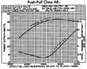
I agree that it only needs to be in the ballpark for performance to be satisfactory. OTOH, considerable power can be lost if the transformer is too far off. Here's an example of the 6L6GB. All else being equal, reducing the load from 6.6K to 3.8K reduces output power by 32%. That's not insignificant.

Screen Shot 2025-02-24 at 9.02.28 PM.png

And here's the chart for 6L6GCs operating at 450V that clearly shows a large loss in output capability when the p-p load is reduced from the optimum of about 7.5K to 4K.

Screen Shot 2025-02-24 at 9.02.55 PM.png

I'm not searching for some theoretically optimum number that a transformer must reflect. But when everyone's measurements differ by 1,000Ω or more, I think that's not good enough. So, I'm just trying to nail this down to range that seems to make sense in terms of not giving up too much.

Jack
 
The Stancor and Chicago transformers I have match their catalog values when unloaded. The Edcor does as well for whatever that is worth.
But then SAMs claims 4K for the A500 transformers, and I measured 4.2K with an 8Ω load. There are other examples from the past, but I don't recall specifics right now. The bottom line IME is that this isn't being specified using the same process by all manufacturers.

Jack
 
More accurate than typical then. Often the 4 and 16 are pretty much the same but the 8 ohm is off by a noticeable amount.
There may be a somewhat hidden reason for that. Some transformer mfgrs provided an 8Ω tap that was actually 9Ω (winding ratio as determined unloaded). A quick test for this is to apply to an unloaded OPT, 4.00vac between common and 16Ω. You should find approx 2.00vac at 4Ω tap and 2.83vac at 8Ω tap if actually 8Ω and 3.00vac if 9Ω. This difference doesn't seem very significant given the wide variation of speaker impedance. It may be significant in simulations or calculations where feedback is taken from the 8Ω tap.
 
I know I'm late to this party, but I'll throw my own grenade in to see what falls out -- and up front, I'll readily admit to hardly being the last word here on this -- or on anything else for that matter. That said --

It seems to me that the one irrefutable fact in all of this is that Impedance is equal to the square of the turns ratio. I know, I know. Impedance is not simple resistance since inductance and reactance are also part of what makes up the total impedance seen by the tubes, which traditional load lines can't account for because those elements are unique to each transformer and speaker load employed. That's also why tube manuals don't specify effective plate-to-plate load "impedance" under their typical operating conditions offered, but effective plate-to-place load "resistance".

But still, as the impedance rule relates to an unknown transformer being measured and whether it should be measured with a loaded or unloaded winding -- how can a transformer represent two different turns ratios at same time -- one determined from a loaded test, and one from an unloaded test? Obviously, it can't. So irrefutable fact number two is that a transformer's turns ratio -- whatever it is -- is, what it is, what it is, all the time, whether the transformer is loaded or not.

My conclusion then is that the most accurate way to determine the true turns ratio, is to measure it with unloaded windings, as any load will introduce loses to distort that finding.

OK. As at least one data point, measured with unloaded windings, the results I measured with Dynaco transformers agrees very closely with that published by Dynaco for their transformers -- which we thankfully have manufacturer's data for. Now admittedly, the same results don't holdup for Acrosound transformers, which always measure higher than the information states by the manufacturer. So as Jack states, there are obviously a variety of factors involved that seem to lack standardization by manufacturers, at least back in the day, anyway -- if not still today as well.

But to finish my point, if the impedance rule is what it is, and the actual by the count turns ratio within a transformer is what it is, then what of the two different results produced by the two different test methods?

Again, my belief is that the simple reflected impedance presented by a transformer is most accurately represented by the turns ratio as determined using an unloaded turns ratio test, and that the apparent increase in reflected load impedance as determined by a loaded turns ratio test more realistically reflects the same simple reflected impedance, plus losses that bring into play the efficiency of the transformer being measured.

After all, the otherwise increased impedance determined from a loaded winding turns ratio test results in reduced power output -- all else being equal -- which is also exactly what happens when a real world output transformer is inserted between the plates of the output tubes, and the load. Operated as given in the typical operating conditions, the stated power output produced is never achieved in the load in practice, precisely because of output transformer losses.

Over the years then, I've come to rely on the unloaded test as the most accurate way to determine simple reflected impedance by a transformer. But from there, actual power delivered into the load is must be reduced by the very real losses that any transformer has (I find that most are about 81% power efficient ), with any design limitations relative to frequency producing additional losses on top of that. For me, this approach has produced very close agreement with the power output a load line suggests will be developed, and that which is actually delivered.

Based on load lines then, using a transformer whose impedance -- as determined by an unloaded turns ratio test -- matches that of the load line drawn, will allow the power the load line represents to be developed. But all else being equal, redrawing the load line to reflect the impedance that the transformer offers from a loaded turns ratio test will be more indicative of the actual power output the load will receive -- if you chose to want to go about it that way. Personally, I prefer to use a standard power efficiency of 81% and unloaded turns ratio tests, which have always returned very accurate results in my experience.

As I say, I'm hardly the last word on transformer considerations, so I'm more than willing to accept whatever holes that can be poked in all of this -- and I must assume some can. So for those can, please elaborate any if you will . Otherwise, I'm just trying to add my own experience to the mix to offer whatever benefit it may have.

Dave

 
The Peerless 16458 transformers I tested in my W5-M's follow that observed behavior pretty closely.

The secondary voltage ratio, loaded vs unloaded, was measured at 0.92. Power follows the square of the voltage ratio, so power ratio is calculated at 0.84, loaded vs unloaded. My tests were performed at 1 watt equivalent output relative to unloaded conditions at 60 Hz on 16Ω secondary. Doing that same test at 25 watts output would likely produce slightly different results.

Granted, that's using actual measurements vs. estimating plate power from load lines drawn on paper, but it shows only a 5% deviation, which is really close correlation, nonetheless.
 
Jack, do you happen to have a set of old-school 5881s? That's what I used in most HK A500 retrofits, as they have about the same overall height as the 7355 (which means they fit easily under the case, and should be well-sufficient in terms of dissipation. In theory, they should test the same as a 6L6GC of the same era, but it would be nice to have actual empirical evidence. I didn't have good 7355s to test in the last one I had here before conversion, but my after-results were about what I expected with the 5881s (right at 25 watts per channel), with stock power supply voltages and stock bias.

That said- if these transformers behave well at 20K, as Dave mentioned, with EL34s- that would seem to be a great way to use these, if custom amps are being contemplated. Or maybe even KT88s, if the EL34 isn't happy at 20KHz. I'd bet an operating point could be found to make a KT88 work at this B+ and loading, that wouldn't completely blow past the capabilities of the transformers.

Regards,
Gordon.
 
Last edited:
Gordon, the 6L6s I've been using in these tests are NOS USA Sylvania 6L6GB. I have a good supply of these, and I'm planning to use them in most of my conversions where they're appropriate for the voltages, loading and output power involved. The HK A500 is unique in that I have a spare power transformer, so it can be converted into monoblocks for the cost of a second chassis. This arrangement will provide sufficient heater current for either 6L6 or EL34. The output tube sockets can be wired to accommodate these two types without changes, and I'll add bias supplies that can be adjusted for either. My experiments with this amplifier a few years ago used the 6L6GBs as well as NOS 7355 tubes, so I believe the results were valid. I hadn't tested the EL34s with these transformers until last month (as described in this thread).

Yes, I'll test the EL34 at 20kHz after the amps are built. I have to say, it's not clear to me that full power distortion at that frequency is a priority. There's very little energy at those upper frequencies in music, and I don't think an audio amplifier should ever approach this operating condition in real world use. Anyway, if there are any issues, I'll use 6L6GB. I've decided now to scrap the HK driver design in favor of a long tail pair phase inverter. That will increase driver headroom and perhaps reduce distortion at normal listening levels. I followed this approach in my TA7000X conversion, and distortion is very low.

Jack
 
Just to follow up, I now have the two chassis needed to repurpose the A500 output transformers into monoblocks. I have also decided to use the 6L6GB, rather than the EL34. Although the latter makes more power, the 6L6 seems to be a better fit in terms of overall dissipation, power consumption and the capabilities of the output transformers.

I recently performed another round of tests to nail down permissible voltage levels in order to comply with the screen dissipation rating of the 6L6GB. The actual rating is somewhat unclear, because various data sheets don't agree. The 1937 RCA data sheet for a metal 6L6 states 3.5W. Later RCA sheets show 2.5W. A Sylvania sheet for the 6L6/6L6G (metal/ST glass) states 2.7W. I'll be using a variant of the GB with plate dissipation rated at 21W, but there are no indications the screen ratings of these tubes have been similarly increased. Because of this, I decided to measure actual screen dissipation at full output to see how hard the tubes can be pushed without exceeding 2.5W at the screens.

With two 6L6GB installed, the stock power supply provides about +400V to the plates. Rather than feeding the screens with this same voltage as in previous testing, I used a variable bench supply for the screens and added 100Ω resistors to monitor screen current. I then juggled bias and screen voltage to accomplish operating conditions that comply with the most conservative rating for screen dissipation. In the end, the screens dissipate 2.5W at full power when the plates are +400V, the screens are +315V and fixed bias is -33V. The screens idle at less than 1W dissipation with these voltages, and output power at the onset of clipping is 28W. This is a conservative operating condition for the 6L6GB, so these are the values I'll transfer to the monoblocks.

A final note, the tubes I'm using are 1222A, discussed in another thread here:

Proof I'm Crazy

Anyone who builds the A500 into monoblocks but uses the 6L6GC rather than 6L6GB won't encounter such a severe screen dissipation limitation. In that case, screen voltage can be increased substantially, and output power can be expected to increase in accordance with the numbers I posted earlier in this thread.

Jack
 
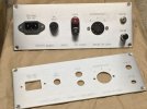
Making some progress with the A500 monoblocks. The layout is finalized in CAD for the top plates, and the rear panels are cut and engraved. The upper panel in the pic has been filled and the parts trial fitted. The lower panel is almost done, still needs to have the engraving filled.

Kyoto A500 rr panels.JPG

Here's the general layout (posted earlier in another thread). I've massaged the exact locations a little since this was shot, but not much difference.

A500 Mono Layout.JPG

The 6SL7 - 6SN7 driver is also now finalized in SPICE.

Almost forgot - the last amp I built had adjustments for AC balance and bias accessible through the chassis underneath. These will have test points and adjustments accessible on top. The look isn't quite as clean, but much more practical. :)

Jack
 
Back
Top Bottom