• The move to the new server is done. There are some software and database maintenance updates in process. This has us passing the hat around to help out. We appreciate any donations. Seriously, even a dollar helps. The payment page may be found here - https://www.audiokarma.org/support.html

HK A500 Output Tube Experiments (Again)

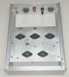
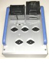
Almost done with the power modules. These will mount under the transformers on standoffs at the rear of the monoblocks. The capacitor board holds all the filter caps for the amps (there are a few more caps under the board). The transformer on the left is for bias. The long turret board has the HV rectifiers and bias supply components. Heaters will be elevated, and there's a provision to adjust heater voltage if necessary.

View attachment 3512163

Jack
Very nice and professional looking stuff! Please show all the audio signal layout. I’m sure it will all be at the tube sockets.
 
Thanks, I'll post the complete schematic once the amps are up and running. I can't finalize the feedback components until then. The original A500 doesn't have a step network or even a phase advance cap. I'm anxious to see how a 10kHz square wave looks without those parts in the new configuration. Yes, the signal path is already wired at the tube sockets as shown in post #51. The only things missing in that photo are the input coax, feedback component(s) and wiring to the OPT. It sure looks empty compared to the power supply.

A couple details need to be dealt with before final wiring. I'm having a problem with one or two of the 8-32 transformer bolts and might need to rethread them. I'm concerned about this because it will probably mean the bolts have to be removed from the transformers. They're wrapped in thin, very fragile paper that I assume is intended to prevent shorting the laminations together. There's also a small choke for the power supply that needs mounting holes drilled and tapped, and I need to add a power switch. All of that is pretty straightforward.

Jack
 
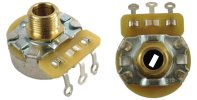
I'm using these CTS 10K bias pots from AES:


1748394684233.png


The pots are attached to the subchassis with standard 3/8" hardware. The subchassis is mounted about 1/4" below the top panel, and a 1/4 diameter hole over each pot allows adjustment from the top. Each of the holes has a nylon hole plug.

IMG_2053 2.JPG
IMG_2055.JPG

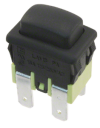
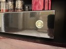
The last thing to decide is the type of power switch to use. I normally mount a push switch on the side of the chassis at the rear to keep it away from signal circuitry. Then I connect a front panel pushbutton to it with a fiberglass shaft. That won't work in this case due to the layout, so I'm searching for a panel-mount switch that will look professional. I'm thinking about these small snap-in switches from Digikey. I'll need to cut a shield to fit the switch on the inside of the panel if I go this route.

Screen Shot 2025-05-27 at 8.21.08 PM.png
Jack
 
I see it now. It looked like the top panel is thick enough that you milled the circular recess.
I used a SS bodied push button switch with LED green ring. I can’t find the part number now. It took me a while to find one that was properly rated. Mouser’s search options sometimes cut the stuff you actually need so I searched through pages of switches and finally found what I needed. They were around $20 a piece though. I think it will look great in your project
 

Attachments

  • IMG_5264.jpeg
    IMG_5264.jpeg
    98.2 KB · Views: 14
Jack -- I'm following your project with interest not only because of your excellent work, but also because I have an A-500 and matching tuner coming here from a client for a makeover in about a month when current work will be finished up.

Regarding your interest in how a 10 kHz square wave will look from the original design since no HF trim components were used, there is likely a good reason for that: If the Sams schematic for the A500 is decently accurate, then based on assumptions I've made from it, the design apparently only uses about 6 db of GNFB, which is little more than ol' Leo used in his Blackface designs, none of which used (or really needed) any HF compensating networks either. It's likely then that no compensation networks were used simply because there wasn't enough NFB applied to really require any.

If you have previously measured the amount of NFB actually applied in the original design, I'd be interested to know how close this estimate is.

Man-oh-man your construction and attention to detail is an inspiration to us all!

Dave

 
Still very much on the lowish side. Did the receiver use any HF compensation networks?

Dave
Not even the phase cap!
It does now, since I increased the feedback to about -12.5 dB.
I remember Jack was surprised when I posted my feedback measurements. I had stability issues and couldn't stabilize it with higher negative feedback. I think that the Positive feedback between the first two triodes has something to do with that, and hopefully not the OT quality.
 
I used a SS bodied push button switch with LED green ring.
That's a nice looking switch! I found it at Mouser, and you're right, they're pricey. Two would cost over $60 with shipping. I already splurged on the heavy anodized handles, so these are probably not in the cards for this build.
the design apparently only uses about 6 db of GNFB
I regret not making this measurement before tearing apart the original amplifier. Mine is using an entirely different driver configuration though, so it didn't seem important at the time. Thanks for your very kind comments on the work!
I had stability issues and couldn't stabilize it with higher negative feedback. I think that the Positive feedback between the first two triodes has something to do with that, and hopefully not the OT quality.
IIRC, my SPICE simulation at one time indicated driver voltage gain of about 340 for this circuit. I was concerned about achieving a stable amplifier with this much gain inside the loop, and it appears you have confirmed the issue. One downside to this design is that despite very good OPTs, NFB is insufficient for really good distortion numbers. Damping is probably also affected by this. Not that it's a bad sounding amplifier. On the contrary, this model was my reintroduction to tube audio almost 25 years ago, and the sound quality is excellent. It was the catalyst for selling off all my SS equipment!

Jack
 
I have something that gets worse with an HF trim setup off the first plate. The squares get goofy, distortion at 20khz goes way up, and its actually more prone to instability. None of that makes a lot of sense to me but everything I tried made it worse, so I just left it all out. Its got just a phase advance cap at this point. Near 20db of feedback too.
 
I've used some ring light type pushbuttons from Amazon. There are many colors and styles available. Here is one that I have used. Most seem to be rated for 12.6V to the LED but I've used them on both 5V and 6.3V. Not so bright this way too.

 
That will require a relay to switch the 120V input. The switch I pictured is rated for 250VAC. I don't remember the amperage rating, but I wouldn't use it if it was not rated correctly
 
The switch which I linked is rated 5A at 250VAC and 5A at 30VDC. It's only the LED that runs on low voltage.
 
Well, now I'm thinking about adding a level control to the front panel and using rotary switches for that and for AC power. Maybe I'll make custom aluminum knobs. Plenty of time to decide, it's the last thing that has to be done after wiring and tuning the amps.

Jack
 
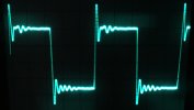
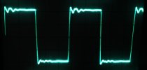
One of the amps is completely wired now except for the power switch and miscellaneous items on the front panel. I set bias to 40mA per tube and ran a few quick tests. NFB is driven off the 16Ω tap, same as the original factory design. Feedback connects to the top of a 1K cathode resistor under the 6SL7 input stage. A 33K resistor in this configuration produces almost exactly 20dB feedback. I stabilized it using an 18pF phase advance cap. Small signal frequency response is flat to beyond 100kHz. More testing will follow once the second amp is wired and everything else is done. Meanwhile, here are the 10kHz square wave results. The first trace shows the feedback resistor alone; the second is with the advance cap.

IMG_2062.JPGIMG_2063.JPG

Jack
 
@TriodeLuvr, do you dampen the OPT peak first with the phase advance cap, then dial-in a step network (if needed) or vice versa? I know the post above is just a "first pass" at stabilization and probably a "curiosity test".
 
The process I use depends on initial square wave results and frequency response. In this case, I think it's good to go. The output transformers perform well and nothing more appears to be needed. My last "reconstructed" amp was different.The OPTs were much more limited, and the factory used an advance cap, step network and also a Zobel across the output to tame the circuit. My version used a completely different driver design, so factory values for the feedback and step networks weren't appropriate. I did use the original Zobel values (thank goodness, one less thing to juggle). In the end it was all trial and error to find a combination of advance cap and step network to stabilize the circuit and create a reasonable square wave. The trick was to accomplish this without curtailing the high frequency response. I spent a lot of time massaging the values, and I'll bet the factory had done the same thing. It was really a struggle to keep it flat out to 20kHz.

Jack
 
Back
Top Bottom