• The move to the new server is done. There are some software and database maintenance updates in process. This has us passing the hat around to help out. We appreciate any donations. Seriously, even a dollar helps. The payment page may be found here - https://www.audiokarma.org/support.html

HK A500 Output Tube Experiments (Again)

my understanding of the load impedance v screen voltage is that higher screen voltage allows for a lower Z transformer. Not sure what you're running or if you have experimented with that but it might factor in here. Only so much you can wind it up before the screen dissipation is excessive though. Also I suspect but have never bothered to confirm that the lower the load impedance, the more the screen current will shift from idle to full output. Swing that too far and it might end up being hard on the tubes even if idle conditions are OK.
 
Yes, higher screen voltage allows maintaining output power as the load impedance decreases. The prototypes of these amps output 33W continuous with the screens at +400V. I don't believe screen current increases significantly though simply by reducing the load impedance, assuming all else remains the same (including output power). In any event, these amps use a 0B3 in series with B+ to reduce the screens to about +310V. That wouldn't be necessary with 6L6GCs, but I have enough of these NOS uprated (21W) 6L6GBs to probably last my entire life. The difference in output power available with the GC isn't worth downgrading to the reissue tubes IMO. Plus, the amps now meet my original goal of ~25W output power. I'm more comfortable operating conservatively like this than pushing everything to the limits like I did with the prototypes. :)

Jack
 
My own 6L6 amp build runs old school 19 watt metal tubes. Thats more conservative design-center though, so design max is a bit higher. 415 on the plates vs 360 rating, but 250 on the screens v 270, and into a 6.6k load. It does an honest 22 watts out, and plate dissipation is about 16 watts. I probably could have gone with a bit higher Z on the transformers but it is what it is at this point. I guess maybe I could experiment with different secondary loading, they do have 4 ohm taps. I didn't think to measure it beyond confirming the square waves look identical on both taps.
 
My own 6L6 amp build runs old school 19 watt metal tubes. Thats more conservative design-center though, so design max is a bit higher. 415 on the plates vs 360 rating, but 250 on the screens v 270, and into a 6.6k load. It does an honest 22 watts out, and plate dissipation is about 16 watts. I probably could have gone with a bit higher Z on the transformers but it is what it is at this point. I guess maybe I could experiment with different secondary loading, they do have 4 ohm taps. I didn't think to measure it beyond confirming the square waves look identical on both taps.
With a 6.6K transformer and +415V on the plates, the lowish screen voltage is probably the main thing limiting output power to 22W. I suspect you wouldn't gain much by increasing it though. You're limited by the tube ratings, just like I am. You might push it up to 27W or 28W with +300V on the screens (including transformer losses). Sylvania shows 6L6s into 6.6K with +400V plates and +300V screens producing 34 Watts output before losses.
 
I probably should have started a new thread for this build. It's not really an experiment at this point. :)

Here's a quick pic of the current state of the amplifiers. Still have blue tape protecting the handles.

IMG_2078.JPG

Jack
 
With a 6.6K transformer and +415V on the plates, the lowish screen voltage is probably the main thing limiting output power to 22W. I suspect you wouldn't gain much by increasing it though. You're limited by the tube ratings, just like I am. You might push it up to 27W or 28W with +300V on the screens (including transformer losses). Sylvania shows 6L6s into 6.6K with +400V plates and +300V screens producing 34 Watts output before losses.

That was my thought as well, and getting more voltage to the screens would require significant changes to the power supply. More work than its worth I expect. The transformers are physically on the small side for fitment reasons anyway. Matt's rating was 25 watts and I don't think he's overly conservative on that.
 
THD — The 6.6K plate-to-plate load that Hafler and Keroes prescribed for UL operation is in fact optimum — for fixed bias operation. It’s a shame that they never emphasized that point, but I’m sure they chose cathode bias for their initial designs to encourage the simplicity of the build or modification as the case may be. In fact however with cathode bias, 6L6 class tubes in true UL service (43%) do perform best with a 7800 Ohm plate-to-plate load. But fixed bias operation with a 6600 Ohm (H&K specs) load offers significant advantages over 7800 Ohm cathode bias operation, most notably with distortion. Besides the expected power increase produced due to the lower load impedance and regained B+ voltage, both IMD and 20 kHz THD drop significantly with fixed bias operation using the original UL specification. I have worked with a number of designs using both Acro’s TO 300 and Eico’s HF-20/22/35 (7800 Ohm) transformer, and that was the case every time.

Dave
 
Love this thread! Very similar but very different from my build. I too had some problems from getting parts through the big auction site and is hit or miss on different vendors. Got sockets, and small stuff with very little change, ordered a couple more chassis and noted the shipping had gone up "some", but came within a couple weeks, and one I'd previously ordered from wouldn't ship to the US now. Ordered a couple other parts near the 1st of May and are still in shipping limbo.

Anyway, that said, I would also like to see the schemo when you get stuff finalized. I even have a HK A5 that uses the 7355 tubes I can rob trannys from. Not much left on the cosmetic side. Might be an interesting 'junk box' experiment. Thanks for sharing this Jack and keep it coming!
 
I'm engraving the front panels now, then I can do final wiring to the power switches and indicators. I think the schematic is finalized at this point, but I want to listen before putting it "out there." Be back soon. :)

Jack
 
Yay - they're done! Distortion is low, frequency response is dead flat, and I see a little over 25W. Hopefully I can get them off the bench and into the system later this evening. The A500 is the amp that woke me up to the sonic benefits of tubes after many years of working with SS. I can't wait to hear how these sound!

A500 Monoblocks quick.JPG

Jack
 
I'm just now starting to listen. The output selectors are set for 4Ω, so the impedance reflected to the tubes is more in keeping with the needs of the 6L6s, as mentioned above. In this configuration they're definitely more highly damped than the A500, and more so even than my much loved TA7000X. The system might even be a little over-damped now. I'll let them break-in a bit this evening, then try tomorrow on the 8Ω tap. I have to say, the midrange is very crisp and detailed. I wish these shouldered VR tubes didn't have so much getter flash. They're a beautiful lilac color, but extremely difficult to see.

Jack
 
Beautiful job as always, Jack! Most of the shouldered VR tubes showed their color through the top of the tube. That's why you can always see them glowing through the vents of Leslie cabinets: The amplifier is mounted so low inside the cabinet that you are looking down on the tubes through the vents.

I've done my own experiments recently on the effects of amplifier damping level and the impact it has on sound reproduction through a given speaker system, the results of which can be quite significant. There is definitely a sweet spot of personal preference regarding it. As you listen to your new amps, it will be interesting to hear what your comments are regarding the differences noted.

Congrats on the beautiful outcome of your project!

Dave
 
Congratulations with a nice job and an interesting journey that you journaled here. Thank you.

Is there a schematic of the final circuit posted somewhere? Apologies if I missed it.
 
Last edited:
Beautiful job as always, Jack! Most of the shouldered VR tubes showed their color through the top of the tube. That's why you can always see them glowing through the vents of Leslie cabinets: The amplifier is mounted so low inside the cabinet that you are looking down on the tubes through the vents.

I've done my own experiments recently on the effects of amplifier damping level and the impact it has on sound reproduction through a given speaker system, the results of which can be quite significant. There is definitely a sweet spot of personal preference regarding it. As you listen to your new amps, it will be interesting to hear what your comments are regarding the differences noted.

Congrats on the beautiful outcome of your project!

Dave
Thanks for the kind words Dave! The subject of amplifier damping has evolved over the years to focus on the concept that "bigger is better." This is clearly the result of systems designed for the solid state crowd, where damping factors can become astronomical and speakers are designed to need this level of control. But as you probably know, optimum system damping was the focus back in the day. The Q created by the amplifier and speaker is unique to every system, and it has a significant bearing on sound quality. I have several speaker books buried away somewhere that discuss this in detail, and this used to be a concept that routinely needed attention in designing a system. Thus the variable damping controls on some of the legacy amplifiers.

I switched to the 8Ω taps after a few hours of use. Sound quality is improved, and the difference isn't only at the bottom end where damping plays such a critical role. The entire spectrum seems better balanced and more musical, and a slightly harsh edge I was hearing with the 4Ω taps is gone. This might be due to the harmonic signature, which is very different. The 4Ω tap pushes the 2nd harmonic down at least another 10dB or so, leaving the 3rd as the dominant distortion component. The 8Ω tap presents a more typical spectral content, with the 2nd being the highest amplitude and everything else cascading down. This is just a guess of course, that the harmonic signature is the cause, and it would be interesting to hear comments from other A500 owners who try this. Mine is no longer an A500, but perhaps this is a characteristic of the output transformers themselves.

Jack
 
Great job Jack!

Perhaps it is the Pentode sound (spectral content/harmonic signature) you are hearing at its best?
 
I think the higher damping thing somewhat predates solid state. For 15 minutes in the 50s adjustable damping was all the rage and then it went away.
 
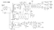
Here are the schematics. To preserve what's left of my sanity, component designators do not "roll over" from one page to the next. Each schematic is separate.

Jack

Kyoto-A500-Amplifier.jpg
Kyoto-A500-PS.jpg
 
Great job Jack!

Perhaps it is the Pentode sound (spectral content/harmonic signature) you are hearing at its best?
I don't know, but I'm really enjoying these amps! Completion of the work coincided with the purchase of several $2 LPs in excellent condition the day before. Listening now to an original 1973 Leo Kottke album. I don't think it has ever been played. It's really remarkable through this all-tube system. Can't stop smiling. :)

Jack
 
Back
Top Bottom