• The move to the new server is done. There are some software and database maintenance updates in process. This has us passing the hat around to help out. We appreciate any donations. Seriously, even a dollar helps. The payment page may be found here - https://www.audiokarma.org/support.html

HK A500 Output Tube Experiments (Again)

The first trace shows the feedback resistor alone; the second is with the advance cap
These OPTs show great promise! I’m amazed and gratified that a measly 18 pF cap can tame that initial overshoot so well. There appears to be gobs of bandwidth to tune out that residual ring if you chose to do so.

My A500 has been sitting in storage since 1985, looks like I need to start gearing up…
 
There appears to be gobs of bandwidth to tune out that residual ring if you chose to do so.
It's important to remember that the ringing is at 180kHz, and that in addition to being beyond audibility, this resonance is triggered by a waveform that won't exist in real source material. A 10kHz sine wave doesn't cause this, or even a 20kHz sine. With the 18pF capacitor that dampens the ringing, a frequency response sweep shows very little undulation until the signal approaches and exceeds 180kHz. I saw a maximum peak of perhaps 1/2dB, and that was above 100kHz. The bottom line is that there's no reason to squelch the residual ringing if the amplifier is stable with these values. A perfect 10kHz square wave isn't the goal; the wave is only being used as an aid to stabilizing the amplifier. Maybe you already know all this. :)

Jack
 
I already know all this. :). Others reading the thread may not. Cary on.
 
Last edited:
Additional testing now indicates good performance from these little amplifiers. Initial distortion measurements were somewhat disappointing, but increasing the cathode current to about 50mA resolved that issue. I'm using the 1222A tube, which is electrically equivalent to an uprated 6L6GB with a 21W anode rating.

Maximum output power really took a hit compared to the earlier tests in the A500 chassis, due to the reduction in screen voltage. It's about 21W at 0.45% THD, which is almost identical to the factory continuous power specification (20W at less than 0.5% distortion). The screens are now at +310V, rather than being powered directly from the +400V B+ line. I was concerned about tube life at the higher voltage, so it's a reasonable trade off. Screen dissipation at maximum output measures about 2.1W, which is within the 2.5W rating for a 6L6GB.

The use of a different driver topology and 20dB of feedback appears to have improved on the manufacturer's distortion numbers. Where HK quotes "5 watts at less than 0.2% distortion," these measure 0.057% THD at that output level. 1W distortion measures 0.032%.

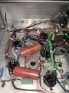
Here are a couple pics of the inside of one amp on the work bench:

IMG_2070.JPGIMG_2071.JPG

This chassis was deep enough to allow physically positioning the heater wiring well above the active circuitry. I like to run it across the chassis space at the top, then drop it down to each socket where it's needed. I almost never twist heater wiring, but I do use tie-wraps to keep it parallel. That works just as well and is much less work. The heaters are also elevated electrically to about +50V. With the input shorted, output hum and noise measure 0.55mV RMS. With the input open, that increases to 0.80mV. These will be quiet amplifiers!

Jack

 
Last edited:
What is the difference between those K40 caps and the more standard ones that come in a bare metal tube?
 
What is the difference between those K40 caps and the more standard ones that come in a bare metal tube?
I have no idea. This isn't a capacitor type I would normally use. They just happened to be in my stash from a purchase 10 or 15 years ago. No listening tests yet.

Jack
 
I have no idea. This isn't a capacitor type I would normally use. They just happened to be in my stash from a purchase 10 or 15 years ago. No listening tests yet.

Jack
So long as they don't leak... I've never had a pink K40Y9 either, just silver. The pink ones I've seen were i think K75? The teflon ones. I also have some green K42Y around which i think are metalized paper in oil, but i haven't had enough coffee to be sure without looking it up.
 
According to internet wisdom, they are coated for thermal protection in higher-temperature environments and to insulate them from accidental shorting against other nearby components. But who knows if that is actually what they are?
 
According to internet wisdom, they are coated for thermal protection in higher-temperature environments and to insulate them from accidental shorting against other nearby components. But who knows if that is actually what they are?
The red paint on these is very thin and chips easily. It couldn't possibly have any real function. I added clear heat shrink to all of them to avoid the possibility of shorts.

Jack
 
I used the bare version twice and heat-shrank them too. I don't remember if the outer shell is connected to one of the leads, but I don't believe so. It's just a conductive chunk on leads that can short out between other components in the chassis.
 
It's not connected to either lead, I've used them a number of times and if they're not near bare wires I don't worry about it, if they are I put some heat shrink over the casing.

@TriodeLuvr what's the power at 20Hz?
 
what's the power at 20Hz?

(Edited)

Output power is the same at 20Hz and 1kHz - a little more than 20W continuous. In fact, it will do this down to 10Hz.

It's worth noting again that the prototype produced 36W continuous output with a pair of EL34 outputs. That was flat down to at least 20Hz. The HK transformers in the current configuration and power level are just loafing.

Like most amps, output power is highly dependent on line voltage. I checked again this evening with the line at 122VAC, and output power is slightly more than 25W continuous (20Hz to 20kHz).

Jack
 
Last edited:
More experimenting has opened another possible area of improvement for the 6L6s. This tube type needs a higher impedance load for optimum performance, and that's why the 7355 performs better with the HK transformers. With this in mind, I moved the output selector to the 4Ω position to see how doubling the reflected load might affect it. This isn't really optimum either, because now the load impedance is on the "other" side of the curve. Output power went up slightly, but only a watt or so. The real improvement was in distortion, which fell to .009% at 1W. Looking at the spectrum, the 2nd harmonic has practically disappeared into the noise. Full power frequency response is still flat to 20Hz, but just barely. It rolls off quickly below that, and this is the tradeoff. Using the "correct" output tap, low frequency response at this power level (25W) is flat to about 14Hz or 15Hz. Overall, performance is probably more than satisfactory using either tap. An extended listening test is probably in order before making a final decision. It's time now to complete the work on the front panel and a few other mechanical details.

EDIT ADD: The change to the 4Ω tap also reduced amplifier sensitivity. It's now about 0.95V RMS for full output. That would be more usable in my system as long as there's no sonic penalty for this.

Jack
 
Last edited:
More experimenting has opened another possible area of improvement for the 6L6s. This tube type needs a higher impedance load for optimum performance, and that's why the 7355 performs better with the HK transformers.
When I switched from the usual 6.6k primary impedance for my Williamson UL's to 7.6k, there seemed to be a sonic improvement although the power, distortion, frequency response, etc remained nearly the same. The 807/1625's (6L6 family) seem to like the higher reflected load as documented in past periodicals of yore.

One pair of my Williamson UL amps uses OPT's with a single 6 Ohm tap... running an 8 Ohm load of them increases the reflected impedance even higher than 7.6k and the sound quality is great.

The sound is a bit sweeter with the 7.6k (or higher) in my opinion.
 
It would be interesting to know whether @GordonW ever tried using the lower-Z taps. He swapped in 6L6s for the 7355 tubes in his A500.

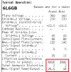
Here's one chart that highlights the issue:

6L6GB Loads RCA.jpg

Voltages applied to the tubes in the A500 are even lower than this, about +330V B+ and +320V screens. There's some disagreement here regarding the primary Z of the HK transformers, but my measurements indicate the primary to be about 4.2K when the secondary is loaded. This number works really well according to 7355 data sheets, but as shown above, it's not so great for the 6L6. Various graphs for the 6L6 also clearly show that optimum power and distortion occur around 7K or a little higher. It's really a shame no one ever produced a reissue of the 7355. Its characteristics are very much like a small EL34, and that would have a lot of potential applications.

Jack
 
According to internet wisdom, they are coated for thermal protection in higher-temperature environments and to insulate them from accidental shorting against other nearby components. But who knows if that is actually what they are?
That's interesting. I used to put clear shrink on the silver ones to accomplish the same thing.
 
Back
Top Bottom