

You are using an out of date browser. It may not display this or other websites correctly.
You should upgrade or use an alternative browser.
You should upgrade or use an alternative browser.
HK A50K one side not playing in stereo
- Thread starter oldman55
- Start date
-
- Tags
- a500 a50k harmon kardan

oldman55
Well-Known Member
yeswhat do you mean with it in mono it plays on the pin 7 channel? Mono using the blend control?

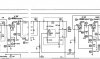
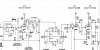
the fact that jumping 2 to 7 with the blend control set to stereo doesn't give you 2 channels implies there is a fault from the grid of the tube downstream. This seems to contradict what was happening earlier.
since the blend control set to mono gives output to both channels, that means everything downstream of that control is working. Thats useful since it means the tone controls aren't messed up. It also isolates the fault from the grid of the tube to the blend pot. Thats the tube itself, the couple of resistors going to it, the output coupling cap, and the connection from the output coupling cap through the high cut switch to the blend pot.
Can you re-check the voltages on V3?
since the blend control set to mono gives output to both channels, that means everything downstream of that control is working. Thats useful since it means the tone controls aren't messed up. It also isolates the fault from the grid of the tube to the blend pot. Thats the tube itself, the couple of resistors going to it, the output coupling cap, and the connection from the output coupling cap through the high cut switch to the blend pot.
Can you re-check the voltages on V3?
oldman55
Well-Known Member
Can you re-check the voltages on V3?
Reconnected circuit to pin2 and with a different V3 valve, measurements are:
Pin1-196vdc
Pin3-1.18vdc
Pin4-10vdc
Pin6-177vdc
Pin8-1.38vdc
pah. That still looks entirely reasonable. I honestly don't understand it. If jumping it at the grid doesn't get 2 channel output but using the blend control does, that means its something at the tube but those voltages look like a tube stage that is working. The not-working side is pulling slightly more current but that could easily be tube differences or off-value parts, not enough to make it not function.
oldman55
Well-Known Member
pah. That still looks entirely reasonable. I honestly don't understand it. If jumping it at the grid doesn't get 2 channel output but using the blend control does, that means its something at the tube but those voltages look like a tube stage that is working. The not-working side is pulling slightly more current but that could easily be tube differences or off-value parts, not enough to make it not function.
Just verified again. Nothing jumping pin2 to pin7 in stereo. As usual, channel works when turning blend to mono.

Edit: Observation; When playing the good channel in stereo its volume lowers (not to where it would affect play) as you turn the blend to mono. Another observation; quality sound. I'm starting to enjoy listening to this unit in mono,
Last edited:
oldman55
Well-Known Member
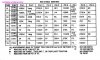
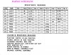
Another observation from looking at the resistance charts. I didnt bother with the directive in regards to switching, just looking for problems.
plin1 0 ohms
pin2 216k ohms
pin3 2.7 ohms
pin4 16 ohms
pin6 0 ohms
pin7 211k ohms
pin8 2.6k ohms
pins 1 and 8 look out of whack looking at the values of V2 on the other chart. The two values given on the "Barney" chart make the valve appear in line.
plin1 0 ohms
pin2 216k ohms
pin3 2.7 ohms
pin4 16 ohms
pin6 0 ohms
pin7 211k ohms
pin8 2.6k ohms
pins 1 and 8 look out of whack looking at the values of V2 on the other chart. The two values given on the "Barney" chart make the valve appear in line.
Last edited:
I was working off that second schematic since it agrees with the full A500 owners manual. Thats V3 per the people who made it.
3 and 8 should read about the same. 2.7 ohms vs 2.6k doesn't jive, unless you dropped a letter there. Only thing on that circuit to ground is the cathode resistor and the capacitor. Often a cap will show as close to being shorted, so that might explain the 2.7 ohm reading. I'll assume that to be the correct value since the pin 2 side of the tube is the one that is working. The 2.6k one might imply that cathode cap is open. That will considerably reduce gain in the stage. It won't make it pass zero signal but it will drop the output level quite a bit without affecting the voltage readings at the tube. It might explain these problems.
I am surprised 1 and 6 read zero ohms though. I'd expect not less than ~270k.
4, 5 and 9 is on the heater circuit, readings there don't really matter.
3 and 8 should read about the same. 2.7 ohms vs 2.6k doesn't jive, unless you dropped a letter there. Only thing on that circuit to ground is the cathode resistor and the capacitor. Often a cap will show as close to being shorted, so that might explain the 2.7 ohm reading. I'll assume that to be the correct value since the pin 2 side of the tube is the one that is working. The 2.6k one might imply that cathode cap is open. That will considerably reduce gain in the stage. It won't make it pass zero signal but it will drop the output level quite a bit without affecting the voltage readings at the tube. It might explain these problems.
I am surprised 1 and 6 read zero ohms though. I'd expect not less than ~270k.
4, 5 and 9 is on the heater circuit, readings there don't really matter.
oldman55
Well-Known Member
Just to be clear and note that it is curious but there are two different full A500 owner manuals:I was working off that second schematic since it agrees with the full A500 owners manual.
https://www.dropbox.com/sh/p468wt98wowyyjk/AACNv5FHK8ceU9fyrbWFllCsa?dl=0
You are correct on my error. It is 2.7K and not 2.7.3 and 8 should read about the same. 2.7 ohms vs 2.6k doesn't jive
Both caps are on the money.The 2.6k one might imply that cathode cap is open
Dont know if it matters but, when measuring resistance on the upstream side of the .2 cap, I get 0 on the pin2 cap and 50k ohms on the pin7 cap. This is a measurement from the pre pin side of the cap to ground.
Verified again.I am surprised 1 and 6 read zero ohms though. I'd expect not less than ~270k
oldman
how about we agree to work from the complete factory A500 manual with operating instructions rather than the SAMS. the HK manual calls it V3. Its a cleaner scan anyway.
still not seeing why 1 and 6 would read 0 ohms. 270k from the power source, and an 0.2 cap out to the filters. Unless there was some residual voltage in the filter cap throwing it off perhaps.
don't know. Nothing I understand about how this should work jives with the test results.
still not seeing why 1 and 6 would read 0 ohms. 270k from the power source, and an 0.2 cap out to the filters. Unless there was some residual voltage in the filter cap throwing it off perhaps.
don't know. Nothing I understand about how this should work jives with the test results.
oldman55
Well-Known Member
still not seeing why 1 and 6 would read 0 ohms
The resistance readings table for the schematic we are working from does not show any readings for those pins. It is only the table from the other schematic that has values listed.
I also put a working A50k back on the bench and those pins also read as 0 ohms so I have to assume that the other schematic has different circuitry.
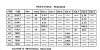
While comparing connectivity to ground on components on the different A50ks, I noticed that all terminals of the High Cut PEC on the non-working unit ring to ground while the working unit only has two, selectively, that ring to ground. This is causing the downstream side of the .2uf coupling cap to be grounded at all times. This is the cap that is connect to the plate of the non-working channel.
But this would not explain, to me, why that channel would play in mono if there is a short in that area. Hope this is not too confusing.
oldman
oldman55
Well-Known Member
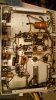
Contour switch, High cut switch, Low cut switch, blend.....what were they thinking? I have a Pilot 110 that rivals "high end" consumer amps on my shelf for sound quality and certainly for reliability. Look at the mess that the marketing dept left to the kit builders. This has all of the controls I need with less signal path, pots and switches to degrade the sound:

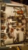
Rant over.
Does identifying the additional issues help to pinpoint the problem or only expand the areas of concern? I havent given up on one yet but this may be the first even though I believe we are close. I just dont have the knowledge to know how the unit would react given certain issues.
Oldman
Rant over.
Does identifying the additional issues help to pinpoint the problem or only expand the areas of concern? I havent given up on one yet but this may be the first even though I believe we are close. I just dont have the knowledge to know how the unit would react given certain issues.
Oldman
Attachments
Last edited:

buickguy62
Active Member
I noticed that all terminals of the High Cut PEC on the non-working unit ring to ground
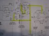
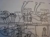
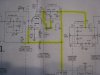
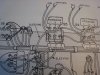
Pin 1 and 3 of the High cut PEC should not be at ground potential. Pin 2 will be at ground only if Hi-cut switch is 'in'. I think you have a short to ground in that wiring which goes to several areas. See highlighted pic. I assume you have the ground in only one of the Hi-cut PECs, with the blend control in stereo. (If in mono, it ties the highlighted wiring to the other channel.
Attachments
buickguy62
Active Member
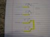
Here's some info, may be of use on how the blend control works. The blend control is a triple pot, the section closest to the front of the shaft controls the mono-stereo lights. The other two sections do the 'blending' of A&B or L&R. In mono, both signals are tied together, and in stereo, they are isolated from each other thru the 100K pots, it's high enough isolate the signals and insulate them from ground.

FlaCharlie
Super Member
I think @buickguy62 has the answer - sounds like you've got a shorted High Cut PEC. Using jumpers, rather than totally disconnecting it from the circuit, doesn't eliminate the short.
I'd suggest that you just bypass the Low Cut and High Cut / Blend sections by disconnecting and wiring around them. The fewer slide switches the better.
The only reason to keep the Low Cut (aka Rumble Filter) and High Cut (aka Scratch Filter) is if you use a turntable. If you do use a turntable you could just bypass the High Cut section and leave the Low alone.
The only reason to keep the Blend is if you plan on listening to a mono source or if, for some reason, you want to reduce the separation of a stereo signal, which is what it does when it's not turned all the way to Stereo or Mono. Of course you can still listen to a mono source without the Blend control by just splitting the signal with a Y connector and sending it to the stereo inputs.
I'd describe the process further but I'm still confused about what schematic you're using and the ones you have posted have an incomplete view of the sections that need to be bypassed.
I'd suggest that you just bypass the Low Cut and High Cut / Blend sections by disconnecting and wiring around them. The fewer slide switches the better.
The only reason to keep the Low Cut (aka Rumble Filter) and High Cut (aka Scratch Filter) is if you use a turntable. If you do use a turntable you could just bypass the High Cut section and leave the Low alone.
The only reason to keep the Blend is if you plan on listening to a mono source or if, for some reason, you want to reduce the separation of a stereo signal, which is what it does when it's not turned all the way to Stereo or Mono. Of course you can still listen to a mono source without the Blend control by just splitting the signal with a Y connector and sending it to the stereo inputs.
I'd describe the process further but I'm still confused about what schematic you're using and the ones you have posted have an incomplete view of the sections that need to be bypassed.
oldman55
Well-Known Member
Thanks for the info from the assembly manual. I'll get into it and maybe even rewire some of the questionable work. I do use a turntable but run it through another pre. Though not useful, I would like to keep the unit as original as possible. Chances of someone parting out a unit where I could get a working PEC should that be the case?
Working off of the schematic in the owners manual:
https://www.dropbox.com/sh/p468wt98wowyyjk/AACNv5FHK8ceU9fyrbWFllCsa?dl=0
Will let you know what I find.
Oldman
Edit: Disconnected one wire from the PEC and the lead was no longer grounded. Makes me think it is the switch that is the issue.
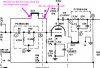
Working off of the schematic in the owners manual:
https://www.dropbox.com/sh/p468wt98wowyyjk/AACNv5FHK8ceU9fyrbWFllCsa?dl=0
Will let you know what I find.
Oldman
Edit: Disconnected one wire from the PEC and the lead was no longer grounded. Makes me think it is the switch that is the issue.
Last edited: