• The move to the new server is done. There are some software and database maintenance updates in process. This has us passing the hat around to help out. We appreciate any donations. Seriously, even a dollar helps. The payment page may be found here - https://www.audiokarma.org/support.html

HK A50K one side not playing in stereo

Though not useful, I would like to keep the unit as original as possible. Chances of someone parting out a unit where I could get a working PEC should that be the case?
I would think that the chances of finding someone who is parting one out is pretty slim.

No problem, though. Just build the PEC circuit on a small piece of perf board. The High Cut consists of 2 resistors and 2 caps. It won't look original - although you could leave the disconnected PEC in place for looks and mount the perf board below deck - but it will function as intended. I'd suggest replacing the High Cut on both channels with new parts.

For now, just wire around it to confirm that it's the problem.

Just disconnect (again, don't just add a jumper but totally disconnect) the wire that goes from the .2 coupling cap to the High Cut switch and pin 1 of the High Cut PEC. Then disconnect the existing wires that go from pin 2 of the High Cut PEC to pin 2 of the Treble PECs. Then run the wires (one from each coupling cap) directly to pin 2 of the Treble PEC for each channel.

This leaves the Low Cut and Blend controls in place and only eliminates the High Cut.
 
Last edited:
I would think that the chances of finding someone who is parting one out is pretty slim.

No problem, though. Just build the PEC circuit on a small piece of perf board. The High Cut consists of 2 resistors and 2 caps. It won't look original - although you could leave the disconnected PEC in place for looks and mount the perf board below deck - but it will function as intended. I'd suggest replacing the High Cut on both channels with new parts.

For now, just wire around it to confirm that it's the problem.

Just disconnect (again, don't just add a jumper but totally disconnect) the wire that goes from the .2 coupling cap to the High Cut switch and pin 1 of the High Cut PEC. Then disconnect the existing wires that go from pin 2 of the High Cut PEC to pin 2 of the Treble PECs. Then run the wires (one from each coupling cap) directly to pin 2 of the Treble PEC for each channel.

This leaves the Low Cut and Blend controls in place and only eliminates the High Cut.

Since the cap going to pin 2 (pin 7 in except) is grounded, wouldn't it be the low cut that has issues? See my edit above.
 
Earlier you said "I noticed that all terminals of the High Cut PEC on the non-working unit ring to ground". Did you mean the Low Cut PEC?
 
Earlier you said "I noticed that all terminals of the High Cut PEC on the non-working unit ring to ground". Did you mean the Low Cut PEC?
The three high cut pec wires rang to ground, none of the low cut did.
old
Excuse my error if I had it backwards.
 
Since the cap going to pin 2 (pin 7 in except) is grounded, wouldn't it be the low cut that has issues? See my edit above.
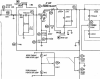
You keep posting very small sections of the schematic and I noticed that the one scanned from the manual is missing some of the parts values in the High Cut PEC - looks like a there was a fold and the scanner didn't read the whole thing.

Here's a broader view of this section of the circuit, taken from the Sams for the A500.

A500 Lo:Hi Cut.png
When you mention caps and pin numbers you need to be more specific. I don't see any cap that's grounded so I have no idea what you're referring to. If you mean C14 (.2 uf), it is not grounded.

OK, I just saw your post where you corrected the confusion about the Low Cut. It is, in fact, the High Cut terminals that show continuity to ground.

It could be that it's just the slide switch (M7) that's shorted, not the PEC. Those old slide switches are known to have reliability issues.

Remove the switch (M7) from the circuit by disconnecting all the wires to it. Then connect the wire from C14, that previously went to the switch, directly to pin 2 of the High Cut PEC and see if you still have issues. If not, it's the switch. If you still have issues it's either the PEC or the Blend pot section. In that case just bypass those sections as I described in my earlier post.
 
Last edited:
something about the readings off the plates of the tube in that section strike me as funny. It should not read to ground. At lowest it should read the value of the plate resistor to ground through the cap on that power supply section. The fact that it doesn't read 0 volts tells me it can't be a dead short though. Might be something is tripping up the meter.
 
something about the readings off the plates of the tube in that section strike me as funny. It should not read to ground. At lowest it should read the value of the plate resistor to ground through the cap on that power supply section. The fact that it doesn't read 0 volts tells me it can't be a dead short though. Might be something is tripping up the meter.
The resistance chart from the manual that he posted earlier is very simplistic and incomplete. And he's not very specific about how he measured.

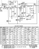
Here's the same tube (labelled V2 in the Sams instead vs V3 in the other schematic) and the Sams resistance chart.
A500 Resistance Chart.png

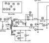
The footnote specifies that the plate measurements (pins 1 and 6 of V2) be made from X2. Here's the portion of the Sams showing X2.

A500 PS.png

I'll bet if he measures according to the Sams the readings will pretty much match the chart at 280k, which is what you say you would expect.
 
fair guess. The disagreement in tube numbers between the assorted schematic scans also makes all this more confusing than it needs to be.
 
fair guess. The disagreement in tube numbers between the assorted schematic scans also makes all this more confusing than it needs to be.
Yeah. Numerous schematics, two different versions of the manual . . . And the fact that at one point he was calling one of the schematics "Barney". :wtf:

I had to read through the entire thread a few times before I started to get even a tenuous grasp of the substance.
 
that was kinda my fault, came out of frustration of what to call this particular tube and the fact the number was added in purple text.
 
From X2 to Pin 1 and 6; I measure 300k and 306k ohms.

still not seeing why 1 and 6 would read 0 ohms. 270k from the power source, and an 0.2 cap out to the filters. Unless there was some residual voltage in the filter cap throwing it off perhaps.

Guess I misspoke; it reads as open when measured from ground.
 
Last edited:
thats a more reasonable number. You're seeing the plate resistor value. Also jives with why the voltages are reasonable.
 
That's good, all looks OK with V2/V3 (based on whichever schematic we use), so probably should next check the wiring of the Hi Cut switch, per FlaCharlie's recommendation above. Note that on that switch (M7) terminals 3 and 4 (from pic from assembly diagram on page 3) are tied together and are properly at ground potential.
 
Appears all wiring is correct. Note that more than just terminals 3 and 4 go to ground as shown on image;
HIGH CUT SWITCH.jpg
 
Then connect the wire from C14, that previously went to the switch, directly to pin 2 of the High Cut PEC and see if you still have issues.
Was trying to avoid removing all connections to the 6 terminals as its tight in there. If I do so and all works, would anything else be needed to have it working except for the bypassed switch, assuming that the switch is the issue? Or do I do the same for the other channel. And what about the disconnected wires, some coming from the low cut switch?

I would have no problem living without the functions of that switch.

Old
 
Last edited:
Ok good, on this switch in the above posting, the bottom half, switch terminals 4,5,6 look to behave as proper.
Now, on the upper half, terminals 1,2,3 all show ground is that correct? Note that terminal 3 should show always ground, but terminal 1 should never show ground, terminal 2 will show ground in one position of the switch, should not show ground in the other position of the switch.

Agreed it is a real chore to remove those connections.

You have two PEC's one for each channel. In both cases the respective pin 2 goes to the center terminal (2 or 5) on the switch.

If the ground is not in the switch, bypassing the switch would not fix the amp. If it is the switch, bypassing would work. If you look at page three where I highlighted in yellow assuming you have pin 2 on one of the PEC's grounded, I think that anywhere on the highlighted yellow, you could have the ground.
 
Last edited:
Appears all wiring is correct. Note that more than just terminals 3 and 4 go to ground as shown on image;
View attachment 1917789
Hard to say what resistance readings are normal. Do a continuity check.

When in the Out position, the only pins 3 & 4 of M7 should be grounded. If either pin 1 or 6 of M7 goes to ground when M7 is in Out position, the signal is going to ground and not reaching the next stage, which = no sound.

Bypass the switch as I described in post above and then listen to the amp to see if the problem is gone.
 
Was trying to avoid removing all connections to the 6 terminals as its tight in there. If I do so and all works, would anything else be needed to have it working except for the bypassed switch, assuming that the switch is the issue? Or do I do the same for the other channel. And what about the disconnected wires, some coming from the low cut switch?

I would have no problem living without the functions of that switch.

Old
I would just eliminate the switch on both channels if that's what the issue is.

Bypassing the High Cut switch (M7) has nothing to do with the Low Cut section, it can stay in place and still function. You shouldn't have any loose wires coming from it.

One step at a time - see if bypassing M7 fixes the problem.
 
Small point, if you remove all the wires on the Hi Cut Switch, (Switch 7) you will lose the ground connection for wire 2 of the Lo Cut PEC's. Wire 2 connects to terminals 3 and 4 on M7, and from there to ground, used as a tie point. In that case, the Lo Cut switch will need to be left in the OUT position, probably not a big deal.
 
In removing wires, I checked C14 and though disconnected from terminal 1 of the switch, the cap still went to ground. The shielded wire connecting it to the switch is shorted internally to the grounded shield as all looks fine externally.

Jumped C14 to the switch and....STEREO. Though not thoroughly tested, I believe all is working properly now.

I know several of you went through a lot of time and trouble to help me but I dont know how I would have ever found a hidden problem in a wire without your help in identifying the location of the problem.

Cannot believe after four pages of troubleshooting that it was just a small piece of wire.

Last question on this; how important is using shielded (sleeving?) wire where indicated?

Again, many thanks for all of the help. This is a great community.

Oldman55
 
Last edited:
Back
Top Bottom