Hi folks,
A couple months I stumbled across some cheap used RCA bi-plate 2a3's (matched pair at 4100 umhos), so a little weak), and decided it was time to dip my toe into DHT SET land. I am not an expert, and relied heavily on AK and other forums to help guide myself, and there was a good amount of stuff I learned that I think could be helpful for other novices building their first DHT amp. The purpose of this post is to help pass on some of the things I learned while doing this, as there were not too many prior examples. Of course, would also love any feedback out there and tweaks to consider from the experts.
Project goal
My goal with this project was to keep parts count down in the theory that the less pieces in the signal path, the greater the transparency (I know this is a very debatable point). I knew I wanted to either directly couple stages and/or have only 1 driver stage. In the end, I decided to do single stage, but de-couple driver and power stage for design executional simplicity, keep the voltages down, and cut down on power transformer needs/cost. Therefore, I embarked on creating a two stage 2a3 amp.
Building the single driver stage:
Single driver stage does cut down on the number of suitable drivers available. This makes a DHT driver somewhat out of the question. I considered using either 6SN7 or 6SJ7 drivers, but concluded I wanted more gain in the single drive stage (one very common design is having 1 6SN7 per channel, two stage driver). The ubiquitous 12ax7 wasn't considered for it's really low current capabilities, and I wasn't keen on the 12au7 for the same reason as the 6SN7. It seemed like using an EL84 pentode could also work (and I had a bunch on hand), but then I came into a pair of NOS D3a for 40 bucks, and my fate was sealed. D3a has fantastic linearity when wired in triode mode, high current drive, and high gain. Some had reported that the D3a could adequately drive 300Bs, and so it seemed like a decent bet for 2a3.
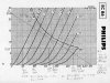
There aren't too many folks who have described their operating points using D3a as a driver for DHT. So, I took matters into my own hands and leaned heavily on https://www.trioda.com/tools/triode.html to draw load-lines. Now, where I made my first mistake trying to minimize stage distortion only using the calculator. This led me to set up my cathode resistor at 35 ohms, B+ at 295V, an anode resistor of 6.2k, with 27ma plate current (max for D3a ~33ma) and ~1V bias. When I first fired up the amp, it sounded okay, but the sound was thick and blurred. I scoured more forums, and found many people were using more like 100 ohms on their cathode, and plate currents ~10-15ma. I steadily increased the cathode resistor value (60, 80, 100, 120 ohm), and found 100 ohm to sounded the best. Then, I varied my plate resistor, and found increasing plate resistance also focused the sound and increased clarity and stereo separation. I settled on setting plate resistance at 10.4k and 100 ohm on the cathode, setting the plate current to ~14ma, bias at ~1.4V, and a plate dissipation of ~2W @ ~145-50V (~1/2 the max a D3a can take). I did do another round of testing different cathode resistor values, but preferred the 100 ohm resistor. I bypassed the cathode with an ultra low ESR e-cap. I have since rigged up a distortion analyzer (probably should have done this a lot earlier) and will be soon be making measurements of the stage distortion to see how distortion changed in real terms as operation point is changed (and probably make a few final adjustments). I'd look forward to someone schooling me on this.
For the coupling capacitors, I had a bunch of russian PIOs and two mundorf supremes hanging around, as well as a pair of miflex KPCU's that I had used in another amp previously. I tried all three, and the Miflex's won out in terms of sound. Mundorf really brightens things up, but becomes harsh after listening for a while. The russian PIOs sound pretty good, but the Miflex's give the sound that "in-the-room" feel while also retaining tons of detail. I think the russian ones lacked a little on the detail. Bang for the buck, the russian PIOs are by far the best. My opinion, YMMV.
Building the power stage
Designing this stage was pretty straight forward. Many folks have implemented 2a3 amps, and the RCA datasheet sets the standard for where to operate 2a3s at. I decided to use cathode bias instead of fixed bias to keep the power supply simple, and I didn't read any strong opinions one way or another on forums.
I kept in mind that my 2a3s were a little weaker than new, and that I would need to tweak things a bit. I also needed to tweak things for the output transformers I had. The RCA datasheet is spec'd for a 2.5k primary OPT, but I had a pair of 3k Electra-print OPTs sitting in the garage that I had from a buddy of mine. This means less power output, but also less distortion. Great. I first designed the stage very much in line with the typical 2a3 operating point: 250V on the plate, 750 ohm cathode resistor, and aimed for 60ma of current. With my weak 2a3, I was only pulling something like 30-40ma, which meant that my bias was also quite low. Playing the amp, the sound was a little thin, so I decided to tweak a bit. I upped the plate voltage to 290V, put a 1k cathode resistor. This meant I was pulling 45ma through each 2a3, producing 45V bias, and dissipating ~11W on the plate (max rating is 15W). The sound was much less thin, bass was much more there. I have kept this operating point. I am a little worried about pushing already weak tubes, but they sound good for now.
A big debate I read about while planning the power stage was DC vs AC filament supply. This is a point some people get militant about on forums (AC causes unacceptable 60hz hum, but DC sounds "sterile" in comparison). This made me first consider DC filaments, but then when i realized I could get a filament transformer for ~10-15 bucks that would power both tubes (you need separate filaments supplies for DHT tubes, if you didn't know like me when I first started the planning), I took the plunge. I was super careful about pathing the 2.5 VAC filament supply wires, and, guess what, this amp is DEAD QUIET. I use this amp with Cornwalls (>100 db/w), and there is zero hum even with my ears pressed against the speakers. I used my scope to adjust the hum balance pot for minimal 60hz, and it is dead quiet. Food for thought as you think about DC vs AC filaments. Probably a good part of my success can be attributed to the wiring/grounding (see below).
Power supply
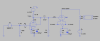
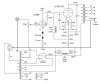
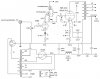
I used PSUD II to help make a low ripple power supply. When designing the power supply, I wanted the option to create a DC filament supply from 6.3V supply, and I wanted to not spend too much on the transformer. This led me to the XPWR007 which offered 6A 6.3V, 275-0-275 at 200ma for only ~60 bucks. To keep choke costs down, I used the 159R from hammond (6H, 200ma, 150DCR). Now, there are a bunch of folks out there that insist on minimal resistance on the power supply line, but I disregarded this advice for better or for worse. I figure that I can reduce the resistance in the future if I want to try to use the same power transformer on 300Bs (maybe not the best idea, as B+ won't be high enough to drive them to full potential). When talking with Jack E of Electra-print, he helped me hone the execution for the power supply, and I took cues from him by adding smoothing capacitors in series bridged by resistors (see schematic). The wall voltage at my house is a little hot (~125-8VAC), so I ended up using the 5V secondary on the PT to buck the mains.
Plinth/chasis
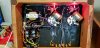
I wanted a wood plinth for appearances sake, and then a metal plate to mount all the components. I was worried with getting a thick enough plate to support the weight of all the transformers without breaking the bank, and settled on 11 x 14 piece of 3/32" inch aluminum (ordered from Metals depot). To cut the holes, you need a drill press. After using a hand drill on other projects and just never getting it 100% right, I went on craigslist and splurged on a drill press for $50 where the guy threw in a bunch of great bits as well... the best $50 i spent. Now, where I screwed up is in painting the metal. Initially I thought a glossy enamel black paint might look good. I was a total idiot, didn't prime the metal, didn't thin the pain. It came out terrible. So, I flipped my drilled plate over, applied a spray primer, black matte spray paint, and then a few layers of poly spray to protect the paint and give it a nice sheen. This came out MUCH better (but the bottom where I mounted I ended up mounting the circuitry looks like a dumpster fire, see the pics). Probably the best thing would have been to get it powder coated, but alas I am a noob in the proletariat. I bought a plank of mahogany from HD, made 45 degree cuts with a mitre saw, glued it together, and then used a router to make the depression for the top plate to sit on. I stained the wood and applied a gloss poly finish.
Wiring and grounding
AC wiring is very commonly a source of serious hum, so I took great care with the filament wire paths to minimize proximity to signal and to use shielded wire for long paths. I routed the 6.3V around the outside edge in shielded wire where it wouldn't cross signal paths. For the 2.5VAC, I did the same, but cheated on one of the channels, twisting the pair of wires to cross ~2 inches above any signal wires. For the low level input signal that traverses the length of the amplifier, I used shielded cables. For grounding, I established a ground bus for the power supply, which I then grounded to the chassis in between the amplifier sections and the power supply. I then routed grounding in series to the amplifier section, which connected to the same chassis ground. I then made sure that there was only the single connection point with chassis. This made me feel pretty good about eliminating ground loops.
Conclusion
The amp sounds very nice. It is a step up from the DG-SE1 (maggie 6BQ5 SEP, which I built guided by the awesome folks on AK ) in transparency and sound stage, at least on my Cornwalls, but not so much that it puts the DG-SE1 to shame at all. I prefer this amp also to my solid state Marantz 1200 on the Cornwalls, as well as a few tube integrated amps that I have hanging around. Most of all, I had a fun time building it and I spent inordinate time reading AK, DIY audio, and other forums to help guide my build. I learned a lot about setting operating points for tubes, and I hope my struggle (esp. with the D3a's), may help some novice builder down the road if they also decide to use D3a's. What I'm going to make sure I have next time when making an amp from scratch is to have the right testing equipment (like a distortion analyzer) as I made the amp. Maybe this would have helped cut down on time fiddling to find operating points that sounded good.
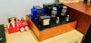
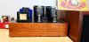
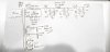
And, it ain't real unless pictures. See attached for a few pics plus the schematic. Would appreciate any thoughts.
A couple months I stumbled across some cheap used RCA bi-plate 2a3's (matched pair at 4100 umhos), so a little weak), and decided it was time to dip my toe into DHT SET land. I am not an expert, and relied heavily on AK and other forums to help guide myself, and there was a good amount of stuff I learned that I think could be helpful for other novices building their first DHT amp. The purpose of this post is to help pass on some of the things I learned while doing this, as there were not too many prior examples. Of course, would also love any feedback out there and tweaks to consider from the experts.
Project goal
My goal with this project was to keep parts count down in the theory that the less pieces in the signal path, the greater the transparency (I know this is a very debatable point). I knew I wanted to either directly couple stages and/or have only 1 driver stage. In the end, I decided to do single stage, but de-couple driver and power stage for design executional simplicity, keep the voltages down, and cut down on power transformer needs/cost. Therefore, I embarked on creating a two stage 2a3 amp.
Building the single driver stage:
Single driver stage does cut down on the number of suitable drivers available. This makes a DHT driver somewhat out of the question. I considered using either 6SN7 or 6SJ7 drivers, but concluded I wanted more gain in the single drive stage (one very common design is having 1 6SN7 per channel, two stage driver). The ubiquitous 12ax7 wasn't considered for it's really low current capabilities, and I wasn't keen on the 12au7 for the same reason as the 6SN7. It seemed like using an EL84 pentode could also work (and I had a bunch on hand), but then I came into a pair of NOS D3a for 40 bucks, and my fate was sealed. D3a has fantastic linearity when wired in triode mode, high current drive, and high gain. Some had reported that the D3a could adequately drive 300Bs, and so it seemed like a decent bet for 2a3.
There aren't too many folks who have described their operating points using D3a as a driver for DHT. So, I took matters into my own hands and leaned heavily on https://www.trioda.com/tools/triode.html to draw load-lines. Now, where I made my first mistake trying to minimize stage distortion only using the calculator. This led me to set up my cathode resistor at 35 ohms, B+ at 295V, an anode resistor of 6.2k, with 27ma plate current (max for D3a ~33ma) and ~1V bias. When I first fired up the amp, it sounded okay, but the sound was thick and blurred. I scoured more forums, and found many people were using more like 100 ohms on their cathode, and plate currents ~10-15ma. I steadily increased the cathode resistor value (60, 80, 100, 120 ohm), and found 100 ohm to sounded the best. Then, I varied my plate resistor, and found increasing plate resistance also focused the sound and increased clarity and stereo separation. I settled on setting plate resistance at 10.4k and 100 ohm on the cathode, setting the plate current to ~14ma, bias at ~1.4V, and a plate dissipation of ~2W @ ~145-50V (~1/2 the max a D3a can take). I did do another round of testing different cathode resistor values, but preferred the 100 ohm resistor. I bypassed the cathode with an ultra low ESR e-cap. I have since rigged up a distortion analyzer (probably should have done this a lot earlier) and will be soon be making measurements of the stage distortion to see how distortion changed in real terms as operation point is changed (and probably make a few final adjustments). I'd look forward to someone schooling me on this.
For the coupling capacitors, I had a bunch of russian PIOs and two mundorf supremes hanging around, as well as a pair of miflex KPCU's that I had used in another amp previously. I tried all three, and the Miflex's won out in terms of sound. Mundorf really brightens things up, but becomes harsh after listening for a while. The russian PIOs sound pretty good, but the Miflex's give the sound that "in-the-room" feel while also retaining tons of detail. I think the russian ones lacked a little on the detail. Bang for the buck, the russian PIOs are by far the best. My opinion, YMMV.
Building the power stage
Designing this stage was pretty straight forward. Many folks have implemented 2a3 amps, and the RCA datasheet sets the standard for where to operate 2a3s at. I decided to use cathode bias instead of fixed bias to keep the power supply simple, and I didn't read any strong opinions one way or another on forums.
I kept in mind that my 2a3s were a little weaker than new, and that I would need to tweak things a bit. I also needed to tweak things for the output transformers I had. The RCA datasheet is spec'd for a 2.5k primary OPT, but I had a pair of 3k Electra-print OPTs sitting in the garage that I had from a buddy of mine. This means less power output, but also less distortion. Great. I first designed the stage very much in line with the typical 2a3 operating point: 250V on the plate, 750 ohm cathode resistor, and aimed for 60ma of current. With my weak 2a3, I was only pulling something like 30-40ma, which meant that my bias was also quite low. Playing the amp, the sound was a little thin, so I decided to tweak a bit. I upped the plate voltage to 290V, put a 1k cathode resistor. This meant I was pulling 45ma through each 2a3, producing 45V bias, and dissipating ~11W on the plate (max rating is 15W). The sound was much less thin, bass was much more there. I have kept this operating point. I am a little worried about pushing already weak tubes, but they sound good for now.
A big debate I read about while planning the power stage was DC vs AC filament supply. This is a point some people get militant about on forums (AC causes unacceptable 60hz hum, but DC sounds "sterile" in comparison). This made me first consider DC filaments, but then when i realized I could get a filament transformer for ~10-15 bucks that would power both tubes (you need separate filaments supplies for DHT tubes, if you didn't know like me when I first started the planning), I took the plunge. I was super careful about pathing the 2.5 VAC filament supply wires, and, guess what, this amp is DEAD QUIET. I use this amp with Cornwalls (>100 db/w), and there is zero hum even with my ears pressed against the speakers. I used my scope to adjust the hum balance pot for minimal 60hz, and it is dead quiet. Food for thought as you think about DC vs AC filaments. Probably a good part of my success can be attributed to the wiring/grounding (see below).
Power supply
I used PSUD II to help make a low ripple power supply. When designing the power supply, I wanted the option to create a DC filament supply from 6.3V supply, and I wanted to not spend too much on the transformer. This led me to the XPWR007 which offered 6A 6.3V, 275-0-275 at 200ma for only ~60 bucks. To keep choke costs down, I used the 159R from hammond (6H, 200ma, 150DCR). Now, there are a bunch of folks out there that insist on minimal resistance on the power supply line, but I disregarded this advice for better or for worse. I figure that I can reduce the resistance in the future if I want to try to use the same power transformer on 300Bs (maybe not the best idea, as B+ won't be high enough to drive them to full potential). When talking with Jack E of Electra-print, he helped me hone the execution for the power supply, and I took cues from him by adding smoothing capacitors in series bridged by resistors (see schematic). The wall voltage at my house is a little hot (~125-8VAC), so I ended up using the 5V secondary on the PT to buck the mains.
Plinth/chasis
I wanted a wood plinth for appearances sake, and then a metal plate to mount all the components. I was worried with getting a thick enough plate to support the weight of all the transformers without breaking the bank, and settled on 11 x 14 piece of 3/32" inch aluminum (ordered from Metals depot). To cut the holes, you need a drill press. After using a hand drill on other projects and just never getting it 100% right, I went on craigslist and splurged on a drill press for $50 where the guy threw in a bunch of great bits as well... the best $50 i spent. Now, where I screwed up is in painting the metal. Initially I thought a glossy enamel black paint might look good. I was a total idiot, didn't prime the metal, didn't thin the pain. It came out terrible. So, I flipped my drilled plate over, applied a spray primer, black matte spray paint, and then a few layers of poly spray to protect the paint and give it a nice sheen. This came out MUCH better (but the bottom where I mounted I ended up mounting the circuitry looks like a dumpster fire, see the pics). Probably the best thing would have been to get it powder coated, but alas I am a noob in the proletariat. I bought a plank of mahogany from HD, made 45 degree cuts with a mitre saw, glued it together, and then used a router to make the depression for the top plate to sit on. I stained the wood and applied a gloss poly finish.
Wiring and grounding
AC wiring is very commonly a source of serious hum, so I took great care with the filament wire paths to minimize proximity to signal and to use shielded wire for long paths. I routed the 6.3V around the outside edge in shielded wire where it wouldn't cross signal paths. For the 2.5VAC, I did the same, but cheated on one of the channels, twisting the pair of wires to cross ~2 inches above any signal wires. For the low level input signal that traverses the length of the amplifier, I used shielded cables. For grounding, I established a ground bus for the power supply, which I then grounded to the chassis in between the amplifier sections and the power supply. I then routed grounding in series to the amplifier section, which connected to the same chassis ground. I then made sure that there was only the single connection point with chassis. This made me feel pretty good about eliminating ground loops.
Conclusion
The amp sounds very nice. It is a step up from the DG-SE1 (maggie 6BQ5 SEP, which I built guided by the awesome folks on AK
) in transparency and sound stage, at least on my Cornwalls, but not so much that it puts the DG-SE1 to shame at all. I prefer this amp also to my solid state Marantz 1200 on the Cornwalls, as well as a few tube integrated amps that I have hanging around. Most of all, I had a fun time building it and I spent inordinate time reading AK, DIY audio, and other forums to help guide my build. I learned a lot about setting operating points for tubes, and I hope my struggle (esp. with the D3a's), may help some novice builder down the road if they also decide to use D3a's. What I'm going to make sure I have next time when making an amp from scratch is to have the right testing equipment (like a distortion analyzer) as I made the amp. Maybe this would have helped cut down on time fiddling to find operating points that sounded good.And, it ain't real unless pictures. See attached for a few pics plus the schematic. Would appreciate any thoughts.