• The move to the new server is done. There are some software and database maintenance updates in process. This has us passing the hat around to help out. We appreciate any donations. Seriously, even a dollar helps. The payment page may be found here - https://www.audiokarma.org/support.html

How can I test the frequency response of an output transformer?

I'll be watchin' that thread! The output transformers sound great with the Mullard 520,but I'm always interested in other options
 
Thanks,Dave!
As usual,your replies have become yet another part of my reference information,You have taught me alot.
I am going to start wotking on the Citation II,I stopped working on it when my mother passed away.
Scott

He's good. :yes:
 
I'll be watchin' that thread! The output transformers sound great with the Mullard 520,but I'm always interested in other options

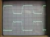
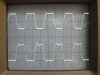
I'll post scope pics at various frequencies. One trace will be the A470 Dynaco on one channel and the other trace and other channel the Conn transformer.
 
Sorry to bring up this old thread, but it appears I have a set of these coming to experiment with.

Where did the 26H come from? And are these 10k p-p trans or 4k (or even 4.8k)? I know I'm missing something here.

It's a 4K transformer, as determined by winding ratio plus losses (loss will be small - primary DCR is only 160 Ohms).

Sorry for my shorthand explanation - the first line of the spec says minimum 10K impedance measured at 100V, 60 Hz, with 10 mA DC applied. So they're specifying a minimum inductance with DC imbalance - 10K inductive reactance at 60 Hz is 26 Henries. Inductance will be higher with no DC (or balanced DC current in both halves). And the inductance is what determines the low frequency response. This transformer will be more tolerant of DC imbalance than the Dynaco.

Leakage inductance is the main factor affecting high frequency response - measured at the primary, with secondary shorted. 22 mH is good, not great (The Dynaco is half that). I did a quick calculation using an oversimplified model - just 22 mH in series with 4K resistive at 20 KHz - I got 4.8K, which isn't THAT far from 4K - so response won't be too far off - and of course feedback can improve that. A real transformer has inter-winding capacitance which can be distributed differently, depending on winding method, so measuring capacitance and leakage inductance doesn't tell you the whole story - you still have to measure frequency response.

Let me know if this all makes sense - it is a complicated subject!
 
The Foster Transformer is the top trace, the Dynaco A470 the lower trace, both at 20 vp-p into 8 ohms (6.25 watts) connected one to each channel of the Millett DCPP Engineer's Amp with 13GB5 output tubes with 460v on the plates and 200v on the screens. Each 8 ohm load connected to the 16 ohm tap for approx 2k p-p load in each case.

At higher outputs at lower frequencies (too low to photograph the scope traces) I get saturation effects of the sine wave with the Foster at 20 Hz before I do with the A470 but not by much. At full power (60 wpc) I really can't see the difference in the traces at 30 Hz, both look quite good.

1. Circuit and showing the sizes of the two types of transformers, they are perfectly identical in side and in weight at 4.75 lbs.
2. 1khz
3. 10khz
4. 20khz
5. 50khz

No global feedback just some anode (schade) feedback applied.
 

Attachments

  • test mule.jpg
    test mule.jpg
    126 KB · Views: 155
  • 1khz.jpg
    1khz.jpg
    52.5 KB · Views: 160
  • 10khz.jpg
    10khz.jpg
    53.9 KB · Views: 156
  • 20khz.jpg
    20khz.jpg
    54.1 KB · Views: 152
  • 50khz.jpg
    50khz.jpg
    60.9 KB · Views: 156
They are perfect for the amp in the pic. They don't have (nor do I need) ultralinear taps. Time to put this amp in a proper chassis and then extended listening.
 
This schematic is for the Artist 720 amplifier(4)7027 (2)7199 (2)7868 (1)12AX7
it is a 3 channel 100 watt amp. in case anyone wants it.
I can't get it posted large enough. If someone wants it I can send it to them.Pm for a copy
 

Attachments

  • conn 720 amp.jpg
    conn 720 amp.jpg
    50 KB · Views: 167
Last edited:
Chipping in very late ....

but there seems to be different ways of testing, related to different points on the performance curve. I grew up with Williamson's suggestions, apparently adopted by a number of manufacturers. OPT inductance will rise with level, thus it was adopted that the lowest level of meaning is 5Vrms into the primary. A leakage reactance standard test seems to be with a signal of 1 kHz, output shorted obviously.

For frequency response of the transformer itself, the OPT must be tested under operating conditions, i.e. the input feeding impedance must be Rl in parallel with tube rp. E.g. for a p.p. EL34 with screen taps, rp seems to be close to 3K per tube, with Rl 6,6K, thus equivalent feeding impedance some 3K over the plate-plate terminals. The secondary is then loaded with the loudspeaker impedance, typically 8 or 4 ohm. A sweep over some 10Hz to above 150 kHz is advised. I prefer manual sweeping as one can advance more rapidly over the flat middle range, and fine tune in the upper h.f. for possible peaks indicating resonance accompanied by phase shift, of importance to later sort out negative feedback stability.

Obviously testing for maximum power (some point near core saturation) and distortion is also informative but requires instruments not generally available to the experimenter.

I hope this is not too old hat; I did not carefully reread the whole thread. In my half-century of designing tube amplifiers I usually found the above sufficient. Other matters rather also involve the electronic design and finally depends on that. (A word of 'sympathy': The poor OPT is often singled out as THE culprit in tube design; I have often found sloppy electronic design as much to blame.)
 
Back
Top Bottom